Checkline Series-5 User Manual
Page 11
Series 5 Digital Force Gauges
User’s Guide
10
Available settings: 1,2,4,8,16,32,64,128,256,512,1024. It is recommended to keep the current reading
filter at its lowest value for best performance, and the displayed reading filter at its highest value for best
stability.
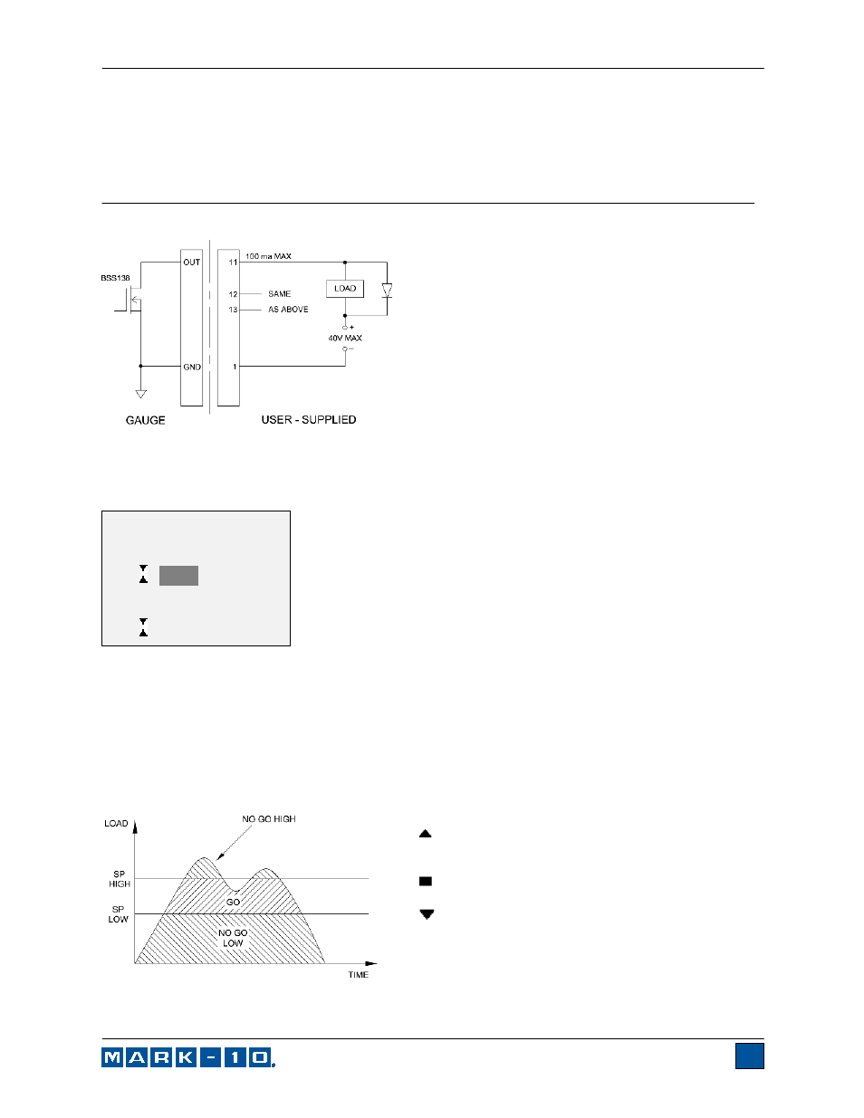
7 SET POINTS
7.1 General Information
Set points are useful for tolerance checking (pass/fail),
triggering an external device such as a motorized test
stand, or alarm indication in process control applications.
Two limits, high and low, are specified and stored in the
non-volatile memory of the instrument and the primary
reading is compared to these limits. The results of the
comparisons are indicated through the three outputs
provided on the 15-pin connector, thus providing “under”,
“in range”, and “over” signaling. These outputs can be
connected to indicators, buzzers, or relays as required
for the application.
7.2 Configuration
To configure set points, select Set Points from the menu. The screen will appear as follows:
Either one, two, or none of the set points may be enabled. To toggle between the tension and
compression directions, press the DIRECTION key.
If two set points have been enabled, they are displayed in the upper left corner of the display. If only one
set point has been enabled, the word “OFF” will appear in place of the value. If no set points have been
enabled, the upper left corner of the display will be blank.
When set points are enabled, the following indicators are shown to the left of the primary reading:
– the displayed value is greater than the upper
force limit (NO GO HIGH)
– the displayed value is between the limits (GO)
– the displayed value is less than the lower force
limit (NO GO LOW)
Set point indicators and outputs reference the displayed reading, not necessarily the current live load.
SET POINTS
Upper Disabled
* Upper Enabled
5.000
Lower Disabled
* Lower Enabled
3.500