Checkline Series-5 User Manual
Page 5
Series 5 Digital Force Gauges
User’s Guide
4
3 MECHANICAL SETUP
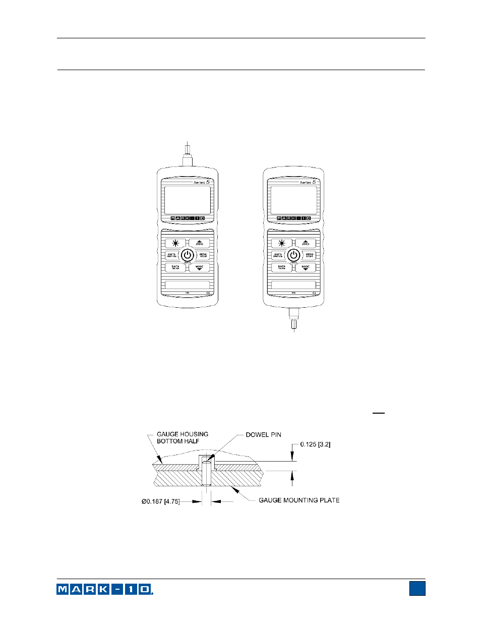
3.1 Loading shaft orientation
In order to accommodate a variety of testing requirements, the orientation of the loading shaft may be set
up in either of the two positions shown below. In order to change the loading shaft orientation, loosen the
two captive screws on the back side of the housing, separate the two housing halves, rotate one half 180
degrees, and reassemble. Contact between the two halves is made by the spring pins and contact pads
on the printed circuit boards.
Load cell shaft up
Load cell shaft down
3.2 Mounting to a plate
Although the gauge may be used by hand, proper mounting is important if attached to a fixture or test
stand. The round steel insert with a hole in the back of the housing is provided to withstand the load
during a test. A mating dowel pin should be used (see illustration below). Mounting plates on Mark-10 test
stands include a dowel pin and clearance holes for the four threaded holes located near the corners of
the housing. These holes are designed to accommodate screws in order to hold the gauge in place
(Mark-10 test stands include a set of thumb screws for gauge mounting). The screws must not be used
for load bearing purposes. Failure to use a dowel pin properly can result in a hazardous situation.
3.3 Mounting attachments to the gauge
The force gauge’s threaded loading shaft is designed to accommodate common grips and attachments
with female mounting holes. To mount a grip, gently thread it onto the shaft. Other mounting adapters are
also available to prevent rotation. Ensure that the grip or fixture is positioned to ensure axial load with
respect to the loading shaft of the force gauge. When using a grip, ensure that it secures the sample in