Appendix a - cone/plate viscometer set-up – Brookfield DV-II+ Digital Viscometer User Manual
Page 20
- 20 -
APPENDIX A - Cone/Plate Viscometer Set-Up
The Cone/Plate version of the DV-II
+
Viscometer uses the same operating instruction procedures as
described in this manual. However, the gap between the cone and the plate must be mechanically
adjusted before measurements are made. This is done by moving the plate (built into the sample cup,
CP-44Y) up towards the cone until two small pins (one in the cone, the second mounted on the plate)
contact, and then separating (lowering) the plate 0.0005inch (0.013mm).
Note that the Cone/Plate Viscometer REQUIRES the use of a good circulating temperature bath
controlling temperature to within (
+
/-) 0.1
°
C. The bath is connected to the ports on the CP-44Y sample
cup.
The following example assumes that the C/P Viscometer is set up on the Model A stand, and has been
zeroed with no cone attached. Cone CP-40 is used in the example. The water bath is on, set at the proper
temperature (the adjustment procedure must be done at test temperature) and is connected to the sample
cup. The Viscometer should be set at 0 rpm with MOTOR ON.
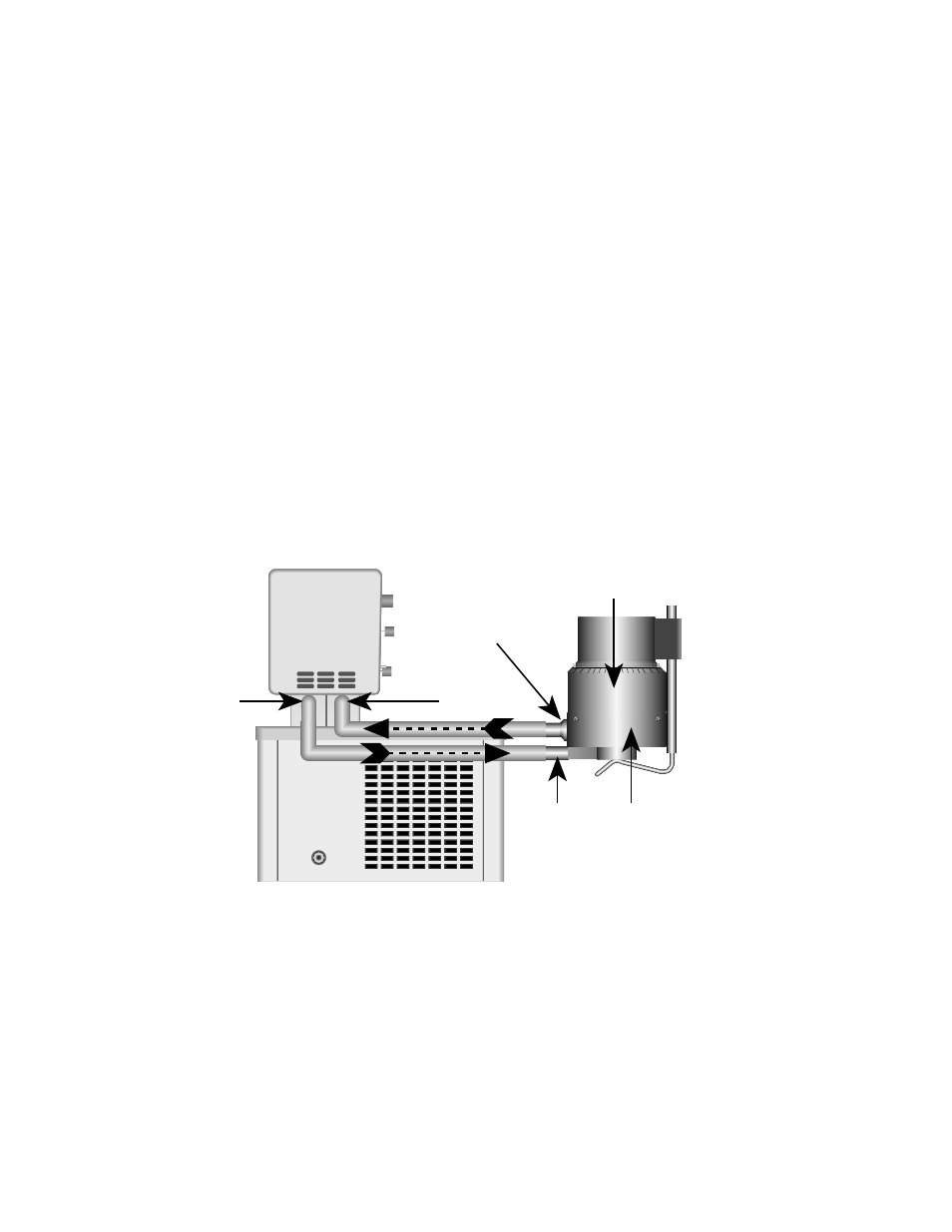
Connect sample cup ports to the water bath inlet and outlet, and set the bath to the test temperature. Allow
enough time for the bath to reach the test temperature (Figure A1).
Figure A1
Remove sample cup and attach the cone to the Viscometer (Note: left hand threads), using the spindle
wrench to hold the Viscometer shaft (Figure A2). Note: Lift up gently on the spindle wrench.
PUMP
INLET
PUMP
OUTLET
Water
Bath
Cup
Inlet
Cup
Outlet
Adjusting
Ring
Bath
Inlet
Bath
Outlet
Sample
Cup
Cup
Outlet
Adjustment Ring
Cup
Inlet
Sample
Cup
Bath
Inlet
Bath
Outlet