Remote control interface – Aviom 6416m/RCI/MCS User Manual
Page 86
75
rci F
ront
P
Anel
F
eAtures
PAD
0.75 AMP
BACKUP POWER
PIN 1 = GND
PIN 4 = 24VDC
AC POWER
FUSE: 250VAC-F4AL
Remote Control Interface
RCI
B
A
+4dBu LINE�LEVEL OUTPUT �BAL�
PIN 2 HOT
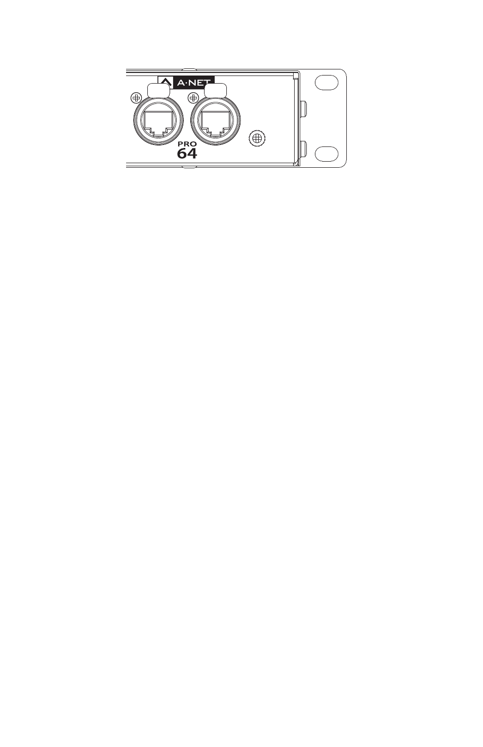
Two A-Net ports are provided, labeled A and B.
When configuring a system, connect a Cat‑5 cable to either the A or B port
when using Auto Mode. In Manual Mode the user must set the front panel
Receive Port settings to reflect where the cables are connected on the rear
panel in order to get the desired result.
Do not plug the MCS Mic Control Surface into the rear panel A-Net ports
of the RCI Remote Control Interface. Plug the MCS into the RCI front
panel Controller port only.