Gpio, Gpio configuration dip switches – Aviom 6416m/RCI/MCS User Manual
Page 72
61
v
irtuAl
d
AtA
c
Ables
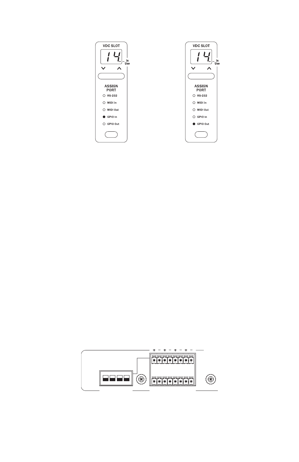
VDC Slot 14 on the 6416m is set to input GPIO
data from the rear-panel jack to the network.
A remote Pro64 device is set to
output GPIO data.
To output control data that originates at the 6416m from another Pro64
module elsewhere in the network, select the same numbered VDC Slot on
the remote Pro64 device that contains the data from the 6416m. Set the
remote device’s VDC type by pressing the selection button to highlight the
data type and light its LED. Press
E
ntEr
to complete the VDC assignment.
To deactivate a VDC Slot, use the selection button to scroll through the data
types until none of the LEDs is lit, and then press the
E
ntEr
button.
GPIO
GPIO (General Purpose Input/Output) can be used to send contact closure
or voltage‑type control signals through the network. Four input and four
output blocks are provided. Each terminal block can be individually wired.
GPIO inputs can be individually configured to be either Isolated or TTL.
GPIO Configuration DIP Switches
Each of the four GPIO Input blocks can be set to either Isolated or TTL
operation using the configuration switches to the left of the terminal blocks.
VIRTUAL DATA CABLE PORTS
AC POWER
FUSE: 250VAC-F4AL
IN
OUT
1 2 3 4
1
2
3
4
RS-232
RESERVED
CONTROL MASTER
1–8
9
10
IN
OUT
ON
RS-232
1.75 AMP
PIN 1 = GND
PIN 4 = 24VDC
BACKUP POWER
GPIO INPUT
UP = ISOLATED
DN = TTL
9–16 THRU (ALT. IN)
1–8 THRU (ALT. IN)
Mic/Line Inputs (Bal) Pin 2 Hot
16
15
14
13
12
11
10
9
8
7
6
5
4
3
2
1
Mic Input Module
B
A
The Isolated/TTL configuration switches only apply to the GPIO inputs.