Warning, Appendix, Co r e c – Steffes 7140 User Manual
Page 42: Co re e core d, Blue, Yellow, A.15 comfort plus commercial hydronic
Appendix
Appendix
n
A.15
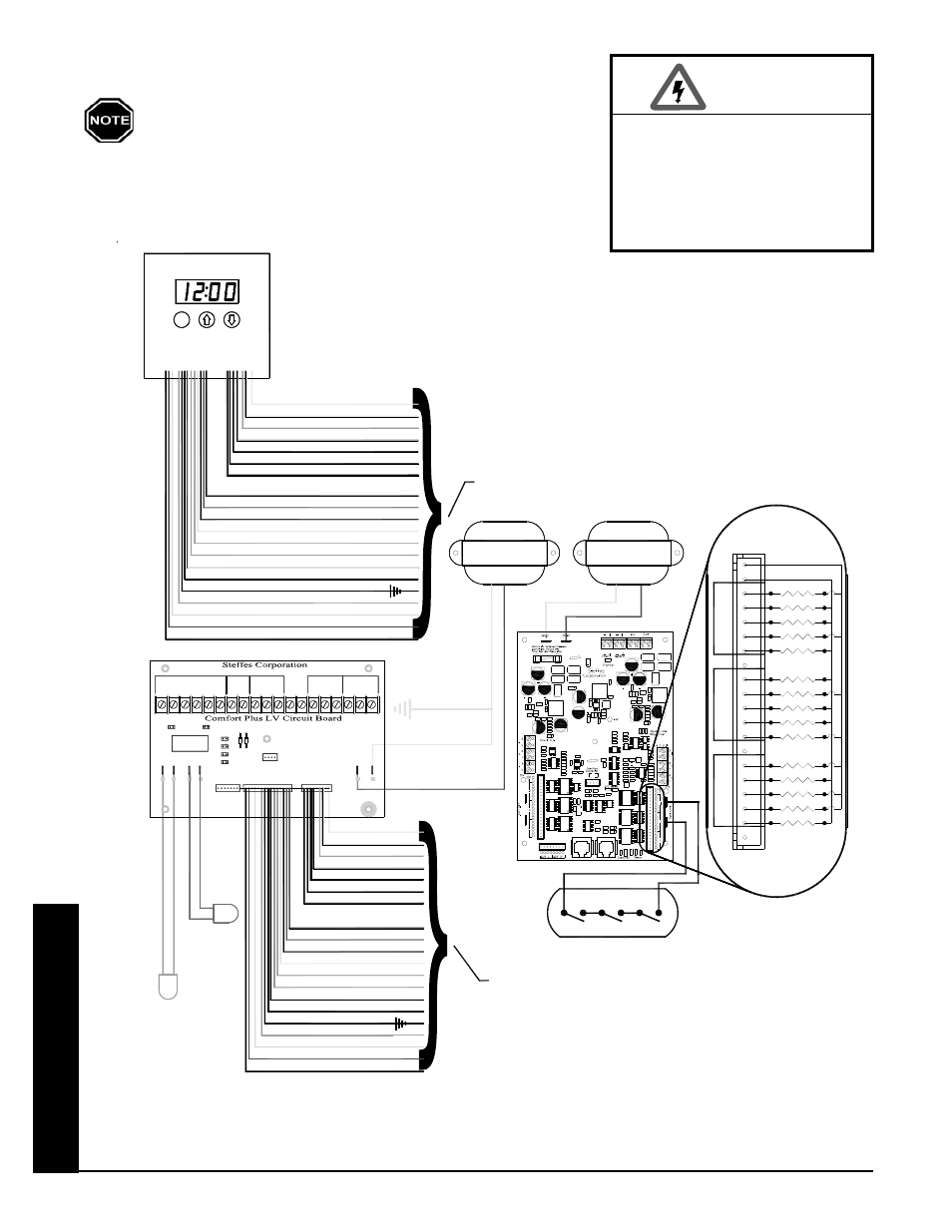
Comfort Plus Commercial Hydronic
"R"
"Y2"
"R"
"O2"
10
9
TO CONTROL BOARD
16
17
20
19
18
11
12
14
15
13
CO
R
E
C
RELAY 2
RELAY 1
RELAY 4
RELAY 3
RELAY 5
20V DC
20V DC
RELAY 15
RELAY 14
RELAY 11
RELAY 10
RELAY 12
RELAY 13
CO
RE
E
CORE
D
RELAY 7
RELAY 6
RELAY 9
RELAY 8
BLUE
18
CORE LIMITS
BLUE
4
7
6
5
8
2
3
1
YELLOW
19
20
YELLOW
UN-GROUNDED
TRANSFORMER
5
GROUNDED
75 VA
TX1
TRANSFORMER
11
12
14
15
16
17
13
6
7
9
10
8
2
1
3
4
TX2
75 VA
TO LOW VOLTAGE BOARD
A
ORANGE/BLACK
YELLOW/BLACK
R
WHITE/BLACK
strip may be used as a source of 24 VAC for powering
The "R" and "C" positions in the low voltage terminal
external low voltage devices (60 VA maximum)
RED
WATER
SENSOR
HANDLER)
AIR
DISCHARGE
SENSOR
AIR
(OPTIONAL
BLACK
BROWN
BLUE/BLACK
GRAY
BLUE
YELLOW
ORANGE
YELLOW/BLACK
WHITE/BLACK
WHITE
GREEN
GRAY
"OS"
DISCHARGE
Relay
Inputs
O
u
tdoo
r
O
u
tdoo
r
Pump
VAC
24
2
Water
P3
P2
P1
Air
P11
W/
Y1
AUX
Y2
J5
Y1 Y2
RLY1
J2
D1
Blower
B
C
D
P4
P5
D2
J4
J3
P6
H/E
Speed
Blower
A
O
G
J6
W/E
Y1
C
R
J1
P
To Control Board
P7
2
Y2
2
O
RP
R
P8
C
P9
NC
AP
COM
NO
Thermostat
Peak
Heat
Aux.
RED/BLACK
WHITE
WHITE/RED
ORANGE
YELLOW
BLUE/BLACK
BLUE
C
"SC"
"RS"
M
CONTROL BOARD
P
M
M
WHITE/BLACK
"NO"
YELLOW/BLACK
WHITE/BLACK
RED/BLACK
WHITE/RED
ORANGE
BLACK
BROWN
YELLOW
GREEN
WHITE
WHITE
RED
"Y"
"O"
"AP"
"P"
"C"
"DS"
"G"
"COM"
"NC"
"W"
"E"
"RP"
NOTE
YELLOW
ORANGE
YELLOW
ORANGE
System Low Voltage Wiring Diagram - 7140 with Variable Speed
The "R" and "C" positions in the low voltage terminal
strip may be used as a source of 24 VAC for powering
external low voltage devices (60 VA maximum).
HAZARDOUS VOLTAGE: Risk
of electric shock. Can cause
injury or death. All low voltage
wiring must be segregated
from line voltage circuits in
the system.
WARNING