Warning, Safety precautions, Safety devices – Steffes 7140 User Manual
Page 3
SAFETY PRECAUTIONS
1. DO NOT energize this heating system while disas-
sembled or without the ceramic heat storage brick in
place.
2. DO NOT operate this heating system without the factory
provided pressure relief valve in place.
3. DO NOT use or store materials that may produce
explosive or flammable gases near the system.
4. DO NOT violate the placement and clearance require-
ments specified in this manual. (Page 3.02-3.03)
5. DO NOT place anything on top of the system.
6. Disconnect power to all circuits before servicing as this
heating system may be connected to more than one
branch circuit.
7. Use caution when working around the heating system as
inlet and outlet piping can be very hot.
8. Installation of and/or service to this system should be
performed by a qualified technician in compliance with
information contained herein and with national, state, and
local codes and requirements.
9. A repeated message display of CORE FAIL indicates
a need for service by a qualified technician.
SAFETY DEVICES
The Comfort Plus Commercial Hydronic incorporates safety devices to ensure normal operating temperatures are
maintained. The chart below describes these safety devices:
Comfort Plus Commercial Hydronic
Safety Information
DEVICE NAME
FUNCTION
LOCATION
ON SYSTEM
Core Charging High
Limit Switches
(Auto Reset)
These limit switches monitor brick core charging and
interrupt power to the heating elements if the normal
operating temperature is exceeded.
This linear limit switch monitors the temperature of the
water in the exchanger and interrupts power to the core
blower if a water temperature of 250
o
F is exceeded. If
this limit switch opens, contact a qualified service techni-
cian.
Heat Exchanger
Limit Switch
(Manual Reset)
In the limit bar panel
on the left side of the
brick storage cavity.
Inside base on left side.
This linear limit switch monitors the temperature of the
water in the exchanger and interrupts power to the core
blower if a water temperature of 225
o
F is exceeded.
Outlet Water
Temperature Limit
Switch (Auto Reset)
Inside base on left side.
Pressure Relief Valve
Factory provided,
field installed to outlet
port of furnace.
If the water pressure exceeds 75 psig, the pressure relief
valve opens. Once water pressure of less than 75 psig is
achieved, the valve closes. (30 psig option available.)
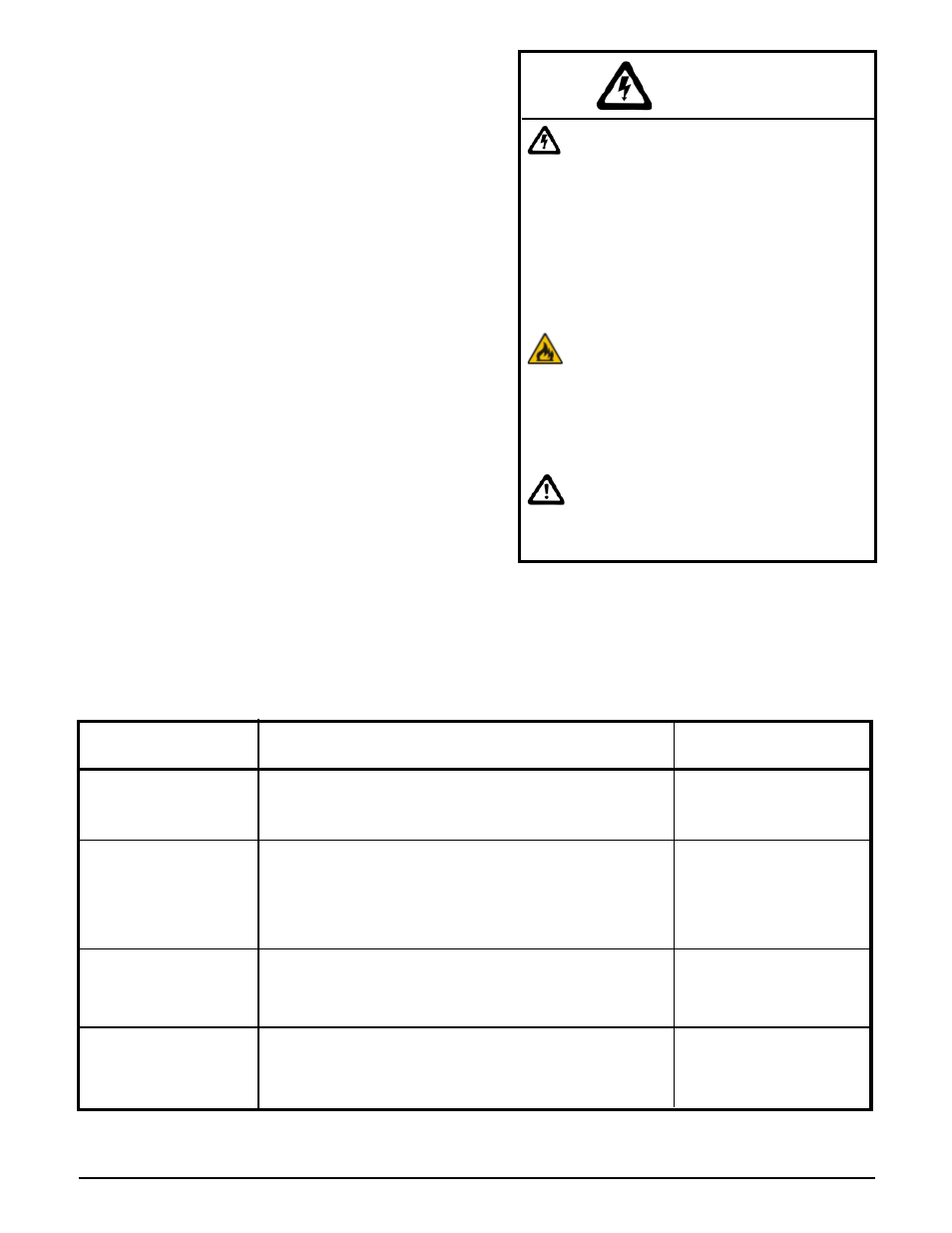
WARNING
Risk of explosion. Can cause injury
or death. Operating the system
without the pressure relief valve
installed can cause an explosion.
Connect the pressure relief valve
in a vertical, upright position with
the supplied fittings. DO NOT
modify this assembly. DO NOT cap,
plug, or otherwise obstruct the
outlet of the pressure relief valve.
Risk of fire. Can cause injury or
death. Violation of the clearance
requirements can cause improper
operation of the equipment. Main-
tain the placement and clearance
requirements specified.
Risk of personal injury. Plumbing
and other surfaces can be hot. Use
caution when working near the
system.