Warning, Brick loading, Heating element and air channel installation – Steffes 7140 User Manual
Page 15
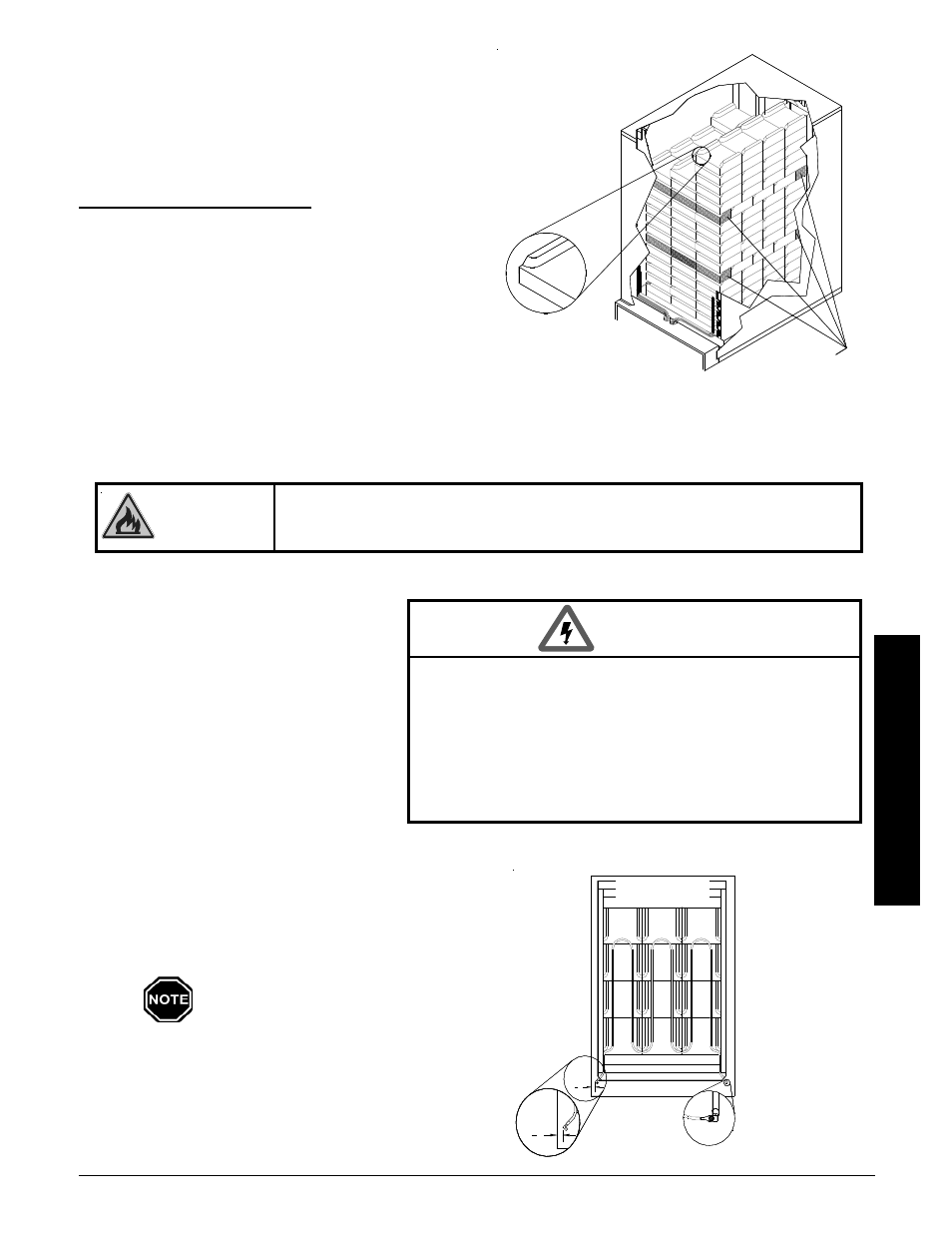
BRICK LOADING
Load the brick, one row at a time, using a left side, right side,
center pattern. Start at the back of the brick core and work
forward. Make sure the brick are placed so the grooved
side is facing up, the notch is facing forward, and the ridges
are on the left and right. (See Figure 4.)
BRICK INSTALLATION TIPS:
Install bricks carefully to avoid damage to the
insulation panels.
Remove loose brick debris to prevent uneven
stacking of brick, as this can make installation of the
elements and the brick core temperature sensor(s)
difficult.
Brick rows MUST line up front to back and side to
side.
Half brick makes brick loading easier by evening out
the stacks. Use HALF BRICK (white boxes) in the
proper rows and positions as indicated in Figure 4. The back half of the brick MUST be installed in the
back row and the front half (the notched brick piece) MUST be installed in the front row.
Risk of fire. Can cause personal injury or death. DO NOT operate the Comfort
Plus Commercial Hydronic system if damage to the insulation panels on the
inner sides of the brick core occurs.
WARNING
HEATING ELEMENT AND AIR CHANNEL INSTALLATION
Step 1 After all brick are loaded, insert the
heating elements between the brick
layers, sliding them in until the
element ends embed into the side
cutouts of the brick cavity.
The elements MUST be installed so
their threaded screw tabs on the
wire connection terminals point
forward and down. If they are
installed with the screw tabs
pointing upward, element-to-wiring
harness connections will be difficult. Elements
must be slid into the brick core properly to ensure
correct clearance between the terminal connec-
tions and any surfaces within the system. Refer to
the required element connection clearance informa-
tion in Figure 5.
In the 277/347 Comfort Plus Com-
mercial Hydronic systems, the sixth
element position up from the bottom
of the furnace is left open.
Step 2 Install the front air channel with the air deflectors
(arrow shaped pieces) facing inward and with the
narrow ends of the deflectors pointing up. Place
bottom portion in first (Figure 6).
Installation
Comfort Plus Commercial Hydronic
Installation
n
3.04
HAZARDOUS VOLTAGE: Risk of electric shock. Can cause
injury or death.
w DO NOT remove the electrical panel cover while
system is energized.
w Position elements properly to avoid short circuiting
them against metal surfaces.
w Protect element lead wires from front panel screws and
any field installed screws to avoid short circuit.
WARNING
ELEMENT INSTALLATION
FIGURE 5
3
4
"
Element Connection
Required Clearance Between
Element Termination and Metal
Panels is 1/2" (3/4" Nominal)
3
4
"
TOP VIEW
BRICK LOADING
FIGURE 4
Fro
nt o
f U
nit
Notch in Brick
HALF BRICK
7120: Load in row 5
7130: Load in row 4 and 8
7140: Load in row 6 and 12