Important, Low voltage electrical connections - peak control, Line voltage wiring diagram figure 10 – Steffes 7140 User Manual
Page 18: Nc p rp com ap no, Installation, 07 comfort plus commercial hydronic, Loop pump primary, 7120 line voltage
6-Position Low Voltage Terminal Block Coding
RP = Peak Control Input Common
P = Peak Control Input
AP = Anticipated Peak (Pre-Peak) Control Input
COM = Peak Control Output Common
NC = Peak Control Output (Normally Closed)
NO = Peak Control Output (Normally Open)
LOW VOLTAGE ELECTRICAL CONNECTIONS - PEAK CONTROL
Steffes ETS heating equipment may be controlled by the Power Company via a
peak control signal. This signal can be sent to the equipment using a Steffes
Power Line Carrier control system, low voltage wiring, a Steffes Time Clock
Module, or line voltage control. In applications utilizing automatic charge control,
outdoor temperature information is required and can be received via an outdoor
sensor or power line carrier control system.
The Comfort Plus Commercial Hydronic system is factory configured for
low voltage peak control and is set to charge when the utility peak control
switch closes. Refer to the Configuration Menu (Pages 3.14-3.15) for
information on configuring the system for the application.
LOW VOLTAGE (HARD WIRED) PEAK CONTROL
If using the low voltage peak control option, the Comfort Plus Commercial
Hydronic is direct wired to the power company's peak control switch. Field
connections from the peak control switch are made to the low voltage
terminal block through a low voltage knockout located on the left side of the
electrical panel.
Step 1 Route a low voltage circuit from the power
companys load control or peak signaling device to
the six (6) position low voltage terminal block inside
the electrical compartment of the Comfort Plus
Commercial Hydronic system through one of its low
voltage wire knockouts.
Step 2 Connect the field wiring to positions "RP" and "P" on
the six (6) position low voltage terminal block. (See Figure 11.)
To use the Comfort Plus to control other loads, refer to Auxiliary Load Control (Page
3.13).
Installation
Installation
n
3.07
Comfort Plus Commercial Hydronic
Low voltage wires
MUST never enter any
line voltage enclosure.
IMPORTANT
JUNCTION BOX INSTALLATION
Step 1 Attach the factory supplied
junction box to the left side
of the Comfort Plus Hy-
dronic Commercial system
as shown in Figure 16
(Page 3.12).
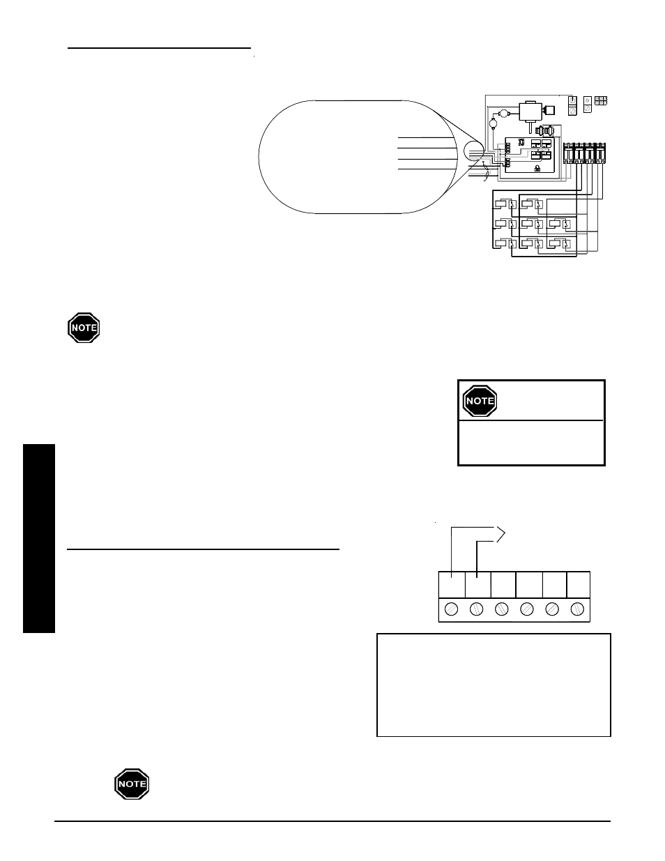
Step 2 Make connections to the
primary loop pump and air
handler pump inside this
junction box. The red and
white wires connect to the
primary loop pump and the
black and white wires
connect to the air handler
pump. (See Figure 10.) The maximum connected amperage on either of these circuits is 1.2 amps.
Step 3 Attach the junction box cover using the screws provided.
PEAK CONTROL
TERMINAL CONNECTIONS
FIGURE 11
NC
P
RP
COM
AP
NO
To Dry Contact Peak
Control Switch
LINE VOLTAGE WIRING DIAGRAM
FIGURE 10
These wires are located in the lower left
corner of the electrical compartment.
WHITE/BLACK
RED
BLACK
WHITE
OR
#2
Element
#1
Element
#3
Element
#5
#8
Element
Element
Element
#4
#7
Element
#6
Element
15A
C
IRC
UI
T
CONT
R
O
L
S
BL
O
W
ERS/
CI
RC
U
IT
#
2
CI
RC
U
IT
#
1
CI
RC
U
IT
#
3
RE
D
BL
A
C
K
BL
U
E
60A
CH
AR
G
E
CH
AR
G
E
60A
CH
AR
G
E
60A
7120 Line Voltage
Use copper or aluminum conductors rated at
Wiring Diagram 208/240 Volt
75° C or higher for field connections of this device.
BLACK
WHITE
EXCHANGER
LIMITS
RESET
225 °
AUTO
MANUAL
N.C.
250 °
TRANSFORMERS
CORE BLOWER
HIGH
COM.
240v / 24v
Cap.
4uf
To Optional Static
Heat Recovery System
BLACK/YELLOW
BLUE/WHITE
ORANGE
BLACK
RED
DAMPER
To Optional Air Handler
5 Amp
5 Amp
RESISTER
RESISTOR
BASE IO BOARD
BL
AC
K/
Y
E
L
L
O
W
ORANGE
BLACK
RED
BLUE
N.C.
RESET
BLOWER
L2 120
L2 240
COM
COM
1/4 Amp
1/4 Amp
NO
NO
COM
COM
SHRU
NO
NO
NO
NO
COM
COM
NO
NO
COM
COM
NEUTRAL LUG
CONTROL CIRCUIT
GROUND
LUGS
L1
BLUE/BLACK
Red & White To Primary
Loop Pump (Max 1.2 AMPS)
Black & White To Air Handler
Pump (Max 1.2 AMPS)
WHITE/BLACK
WHITE
OR
LOOP PUMP
PRIMARY
ORANGE
If utilizing the optional air handler, the orange wire can be used with the white wire to power
a secondary pump for hydronic zones.