Internal system wiring diagrams - line voltage, Appendix, C or higher for field connection of this device – Steffes 7140 User Manual
Page 31: Comfort plus commercial hydronic appendix, A.04, Base io board, Neutral lug control circuit ground lugs
Appendix
Comfort Plus Commercial Hydronic
Appendix
n
A.04
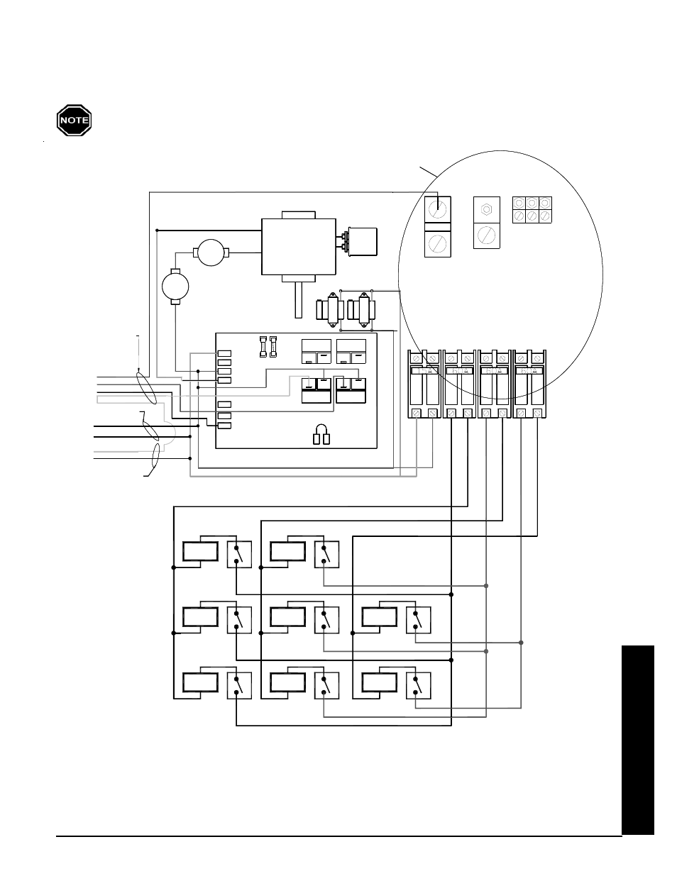
INTERNAL SYSTEM WIRING DIAGRAMS - LINE VOLTAGE
Line Voltage Wiring Diagram - Model 7120
240V OR 208V SYSTEMS ONLY
#2
Element
#1
Element
#3
Element
#5
#8
Element
Element
Element
#4
#7
Element
#6
Element
CIRCUI
T
CONT
R
O
LS
BL
OWER
S/
C
IRCUIT #2
C
IRCUIT #1
C
IRCUIT #3
RE
D
BL
A
C
K
BL
U
E
CHA
RGE
CHA
RGE
CHA
RGE
BLACK
WHITE
EXCHANGER
LIMITS
RESET
225 °
AUTO
MANUAL
N.C.
250 °
TRANSFORMERS
CORE BLOWER
HIGH
COM.
240v / 24v
Cap.
4uf
To Optional Static
Heat Recovery System
BLACK/YELLOW
BLUE/WHITE
ORANGE
BLACK
RED
DAMPER
To Optional Air Handler
5 Amp
5 Amp
RESISTER
RESISTOR
BASE IO BOARD
BL
ACK
/YE
L
L
O
W
ORANGE
BLACK
RED
BLUE
N.C.
RESET
BLOWER
L2 120
L2 240
COM
COM
1/4 Amp
1/4 Amp
NO
NO
COM
COM
SHRU
NO
NO
NO
NO
COM
COM
NO
NO
COM
COM
NEUTRAL LUG
CONTROL CIRCUIT
GROUND
LUGS
L1
BLUE/BLACK
Red & White To
Primary Loop Pump
(Max 1.2 AMPS)
Black & White
To Air Handler Pump
(Max 1.2 AMPS)
WHITE/BLACK
SEE NOTE 2
WHITE
OR
LOOP PUMP
PRIMARY
SEE NOTE 1
NOTE 1: Line Voltage Field Wiring Connections. See Figure 8 for information on proper circuit phasing.
NOTE 2: For more information regarding pump (circulator) wiring, reference Figures 9, 15 and 16 in the
Installation section of this manual.
Use copper or aluminum conductors rated for 75
o
C or higher for field connection of this device.