Steffes 7140 User Manual
Page 29
Appendix
Comfort Plus Commercial Hydronic
Appendix
n
A.02
Appendix
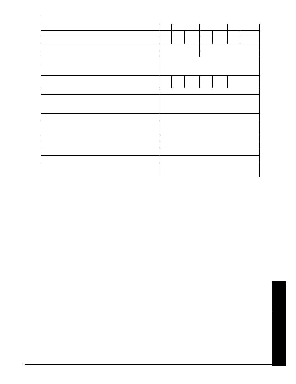
Note 1: 208V or 240V systems are factory configured to be field connected to multiple, single
phase, line voltage circuits. If single feed to element and blowers/system controls circuit
is desired, an optional single feed kit is available to order. Connection to 3-phase power
is acceptable and can improve phase balancing.
Note 2: Because 277V/480V and 347V/600V systems are configured for single feed, three phase
line voltage connections only, a step down transformer must be field installed.
Note 3: The size and heating ability of the system required for an installation is dependent on the
thermal load and the demand profile of the facility. The daily rate structure of the utility
can also affect size of furnace needed in an application. If the unit is not installed within
the heated area, heat lost statically must be taken into account when sizing a system.
Contact Steffes Corporation for assistance in selecting an appropriately sized system.
Note 4: The indoor coil or outdoor compressor of an air conditioner or heat pump are not in-
cluded with the furnace. The Steffes return air plenum (for use with the 6140) and the
Steffes air handler (for use with the 7140 to allow it to provide forced air heating), are
each configured to house an indoor coil and can be ordered from the factory as an optional
accessory. Dimensions listed are that of the inner coil area in the plenum. For larger
coils, field provisions to the factory built plenums are necessary or one will need to be
custom built by the installer. (In heat pump applications, the indoor coil MUST be placed
on the return air side.)
Vo ltag e
208
C harg ing Input (k W)
36
36
42.75 38.4
46.5
36
46.5
Ele me nt C urre nt D raw (A mps )
174
150
179
47
56
35
45
Phas e
N umbe r o f Wire s
C o ntro l C ircuit Vo ltag e (VA C ) - Se e N o te 2
M inimum C ircuit A mpacity (A M PS) fo r 2 4 0 V
C o ntro l C ircuit
Sing le Fe e d M inimum C ircuit A mpacity (A mps ) -
Se e N o te 2
198
233
60
63
75
48
60
Pump Vo ltag e - Se e N o te 2
Sto rag e C apacity - Se e N o te 3
k Wh
B TU
A ppro x imate Ins talle d We ig ht (lbs )
M ax C o il D ime ns io ns (W x D x H ) - Se e N o te 4
Pipe Size (Inle t/O utle t)
Primary Lo o p R e quire me nts
O utput Wate r Te mp - Se le ctio n R ang e
M ax imum Wo rk ing Pre s s ure
Flo w R ate (Primary Lo o p)
*The control circuit for 208 and 240 volt systems must be 3-w ire.
240
50
o
F to 185
o
F
2*
Single
240
3,894
½ H P : 21.2” x 21.2” x 24 ¼”
1 H P : 26.4” x 21.2” x 24 ½”
1”
Minimum of 10’ of 1” pipe
120V (N etural Conductor Required)
818,800
60 P SI / O ptional 20 P SI
1 GP M per 10,000 BTU of required output at
20
o
F temperature rise (10 GP M maximum)
M o de l 7 1 4 0
277
347
208/240
10
Three
4