Caution – Steffes 7140 User Manual
Page 23
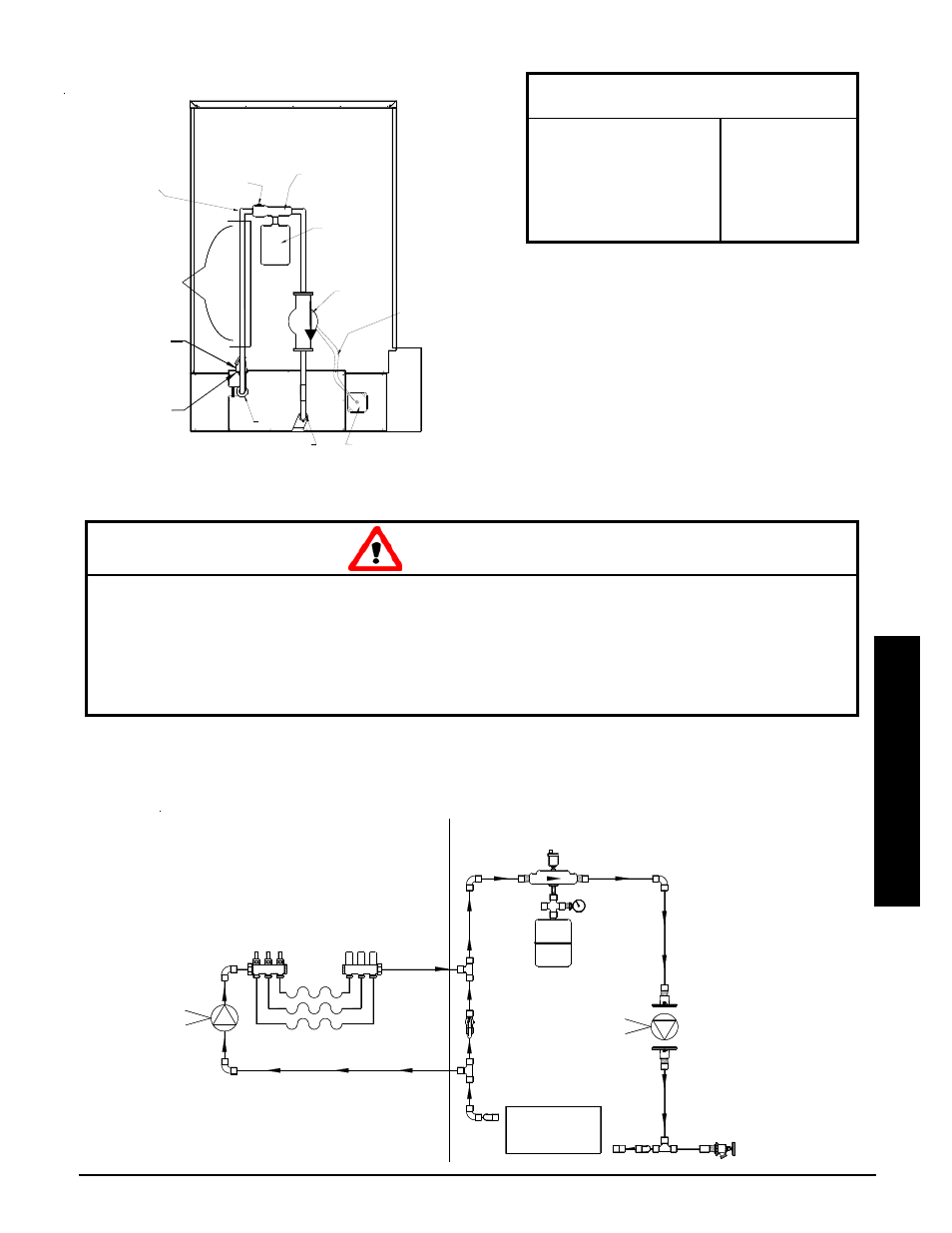
Outlet
Inlet
Zone
Connection
Area
Optional
Temperature and
Pressure Relief Valve
(Consult Local Code)
Pressure
Relief Valve
(Factory Supplied)
Piping MUST Be
Supported
Air Vent
*Primary
Loop
Pump
Junction Box
(Factory Supplied)
Primary Loop Pump
Control Wiring
(White & Red)
Air Separator
Expansion
Tank
STATIC PRESSURE
(Feet Water Column)
Based on 80 degree entry
water temperature with
a 50% glycol mix.
.1 ft @ 2 GPM
.2 ft @ 4 GPM
.4 ft @ 6 GPM
.7 ft @ 8 GPM
1.1 ft @ 10 GPM
PRESSURE DROP THROUGH
HEAT EXCHANGER
TYPICAL SYSTEM PLUMBING
SINGLE TEMPERATURE ZONES
FIGURE 17
TYPICAL PRIMARY LOOP
FIGURE 16
PUMP SPECIFICATIONS
Steffes recommends a Grundfos UP15-42F
single speed 115VAC pump for the
primary pump.
Air Handler pump should NOT be a split
phase pump.
Air Handler pump should NOT have any
type of auxiliary control built into or onto
the pump.
FREEZE PROTECTION: Risk of frozen pipes. Can cause property damage. Hydronic heating system
freeze-ups WILL cause extensive damage to the entire heating system and/or property. It is the re-
sponsibility of the installer to provide protection against freezing.
PIPING SUPPORT: Risk of exchanger damage. Can cause property damage or personal injury. DO
NOT use the exchanger as support for piping. Support brackets should be in place to ensure proper
operation of the system and to keep pressure off the inlet and outlet piping.
CAUTION
Installation
Comfort Plus Commercial Hydronic
Installation
n
3.12
Red
White
This Valve Must
Be Open During
Normal Operation
Exchanger
Primary
Loop Pump
Secondary Loop
Primary Loop
Red
White