Warning, Terminal blocks to low voltage, Board control – Steffes 7140 User Manual
Page 41: Appendix, Yellow, Blue, Core c, Core e core d
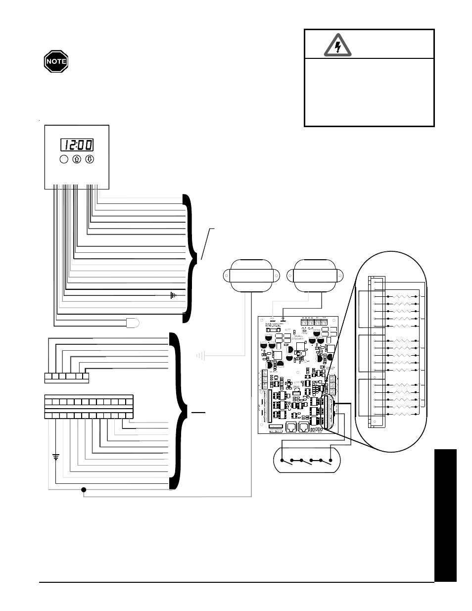
System Low Voltage Wiring Diagram - 7140
The "R" and "C" positions in the low voltage terminal
strip may be used as a source of 24 VAC for powering
external low voltage devices (60 VA maximum).
HAZARDOUS VOLTAGE: Risk
of electric shock. Can cause
injury or death. All low voltage
wiring must be segregated
from line voltage circuits in
the system.
WARNING
Appendix
Comfort Plus Commercial Hydronic
Appendix
n
A.14
"OS"
WATER SENSOR
18
19
17
BLUE
6
Terminals for Connection as a Stand Alone Furnace
R
W
C
Y2
Y
G
Peak Control Connections
RP
COM
AP
P
NO
NC
OS
W2
DS
SC
BLUE/WHITE
5
BLUE/RED
8
BLUE/WHITE
BLUE/RED
BLUE/YELLOW
14
7
15
PURPLE
GRAY/WHITE
GRAY
"SC"
YELLOW
12
11
14
13
10
16
15
WHITE
"W"
BLUE/YELLOW
"AP"
BLACK
BROWN
BLUE/WHITE
"C"
DISCHARGE
"P"
ORANGE
GREEN
YELLOW
"O"
"G"
"Y"
7
BLUE/RED
"COM"
BLUE/RED
RED
8
"RP"
"E"
9
BLUE/WHITE
BLUE
ORANGE/BLUE
5
"NO"
"NC"
6
"O2"
4
GROUNDED
75 VA
TRANSFORMER
TX1
UN-GROUNDED
YELLOW
TX2
75 VA
TRANSFORMER
TERMINAL BLOCKS
TO LOW VOLTAGE
strip may be used as a source of 24 VAC for powering
The "R" and "C" positions in the low voltage terminal
external low voltage devices (60 VA maximum)
CONTROL BOARD
M
YELLOW
YELLOW/BLUE
1
"R"
"Y2"
2
NOTE
P
M
M
A
PURPLE/WHITE
"DS"
3
ORANGE
"R"
CORE C
RELAY 2
RELAY 1
RELAY 4
RELAY 3
RELAY 5
20V DC
20V DC
RELAY 15
RELAY 14
RELAY 11
RELAY 10
RELAY 12
RELAY 13
CORE E
CORE D
RELAY 7
RELAY 6
RELAY 9
RELAY 8
TO
Terminals for Connection with Heat Pump
GREEN
13
YELLOW AND ORANGE
1 & 3
BLACK
YELLOW
YELLOW/BLUE
11
16
2
R
Y2
Y
C
O2
O
G
9
18
WHITE
ORANGE
ORANGE/BLUE
4
12
10
RED
BROWN
GRAY/WHITE
E OS
W
DS
SC
19
17
GRAY
BLUE
CORE LIMITS
BOARD
CONTROL
BLUE