Caution, Warning, Plumbing – Steffes 7140 User Manual
Page 22: Pressure relief valve installation
PLUMBING
The Comfort Plus Commercial Hydronic heating system MUST be plumbed with a primary loop and
secondary (zone) loops. The primary loop needs to consist of a minimum of 10' of 1" pipe and requires its own
pump* (circulator). The secondary (zone) loops require additional pump(s) to operate effectively. Refer to Typical
Primary Loop (Figure 16) and the Typical System Plumbing Diagrams (Figures 17 and 18) for installation information.
The primary loop serves to regulate heat transfer from the systems heat exchanger, therefore, the primary loop must
be powered by Comfort Plus Commercial Hydronic control system.
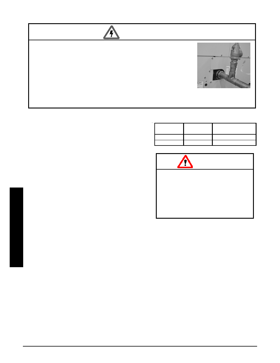
Step 1 Remove the exchanger access panel and locate the pressure relief valve assembly.
Step 2 Connect the pressure relief valve to the outlet
water port on the left side of the Comfort Plus
Commercial Hydronic. It is extremely important
that the following conditions for installation of this
part are met:
· Ensure all connections, including the valve
inlet are clean and free from any foreign
material.
· Use pipe compound sparingly, or tape on
external threads only.
· Mount the pressure relief valve in a vertical,
upright, position directly to the outlet water
port of the system. Under no circumstances
should there be a flow restriction or valve of
any type between the safety relief valve and
the pressure vessel.
Step 3 Use schedule 40 pipe to install a discharge line for the pressure relief valve. This discharge line MUST:
· be connected from the valve outlet with no intervening valve and directed downward to a safe
point of discharge.
· allow complete drainage of both the valve and the discharge line.
· be independently supported and securely anchored to avoid applied stress on the valve.
· be as short and straight as possible.
· terminate freely to atmosphere where any discharge is clearly visible and is at no risk of freezing.
· terminate with a plain end that is not threaded.
· be constructed of a material suitable for exposure to temperatures of 375
o
F or greater.
· be, over its entire length, of a pipe size equal to or greater than that of the valve outlet.
PRESSURE RELIEF VALVE INSTALLATION
Risk of discharged hot water and/or
steam. Can cause personal injury or
property damage. During operation,
the pressure relief valve may dis-
charge large amounts of steam and/or
hot water. To reduce the potential for
bodily injury or property damage,
install a discharge line.
CAUTION
Installation
Installation
n
3.11
Comfort Plus Commercial Hydronic
WARNING
Risk of explosion. Can cause injury or death. The factory supplied
pressure relief valve MUST be connected to the system with the
supplied fittings.
w DO NOT modify this assembly.
w DO NOT cap, plug, or otherwise obstruct the outlet of the
pressure relief valve.
w DO mount the pressure relief valve in a vertical, upright
position.
w This pressure relief valve is sized to service the needs of the Comfort Plus Commercial
Hydronic heating system. If multiple heating systems are being used, pressure relief
valving for the other system MUST be provided separately.
Pressure
Relief Valve
Minimum
BTU Rating
Maximum
Operating Pressure
30 PSI
400,000
20 PSI
75 PSI
500,000
60 PSI