Air conditioner/heat pump interface – Steffes 7140 User Manual
Page 21
AIR CONDITIONER/HEAT PUMP INTERFACE
The Comfort Plus Commercial Hydronic system can be used in conjunction with an air conditioner or a heat pump.
Refer to the optional Air Handler (Page 2.02) and the Low Voltage Connections for Heat Pump Application
Diagram (Figure 13-14), for more information on interfacing these systems with the Comfort Plus Commercial
Hydronic. If multiple heat pumps are being interfaced, contact Steffes Corporation.
Installation
Comfort Plus Commercial Hydronic
Installation
n
3.10
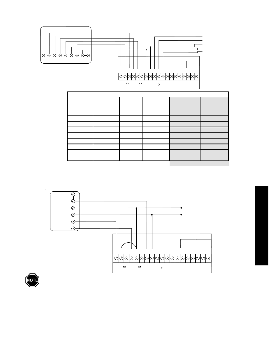
STAND ALONE FURNACE APPLICATION WITH VARIABLE SPEED BLOWER
CONNECTIONS SHOWN FOR SINGLE STAGE HEATING / SINGLE STAGE COOLING
(UNCONTROLLED AIR CONDITIONING)
FIGURE 15
If installing a mechanical thermostat or thermostat with anticipator, a resistor kit is required
(Order Item #1190015).
IMPORTANT
и
Б
Б
Б
!
"#
В
$%$
&'
(#
()
*" +
,$$- .$. + $/$%"+ ( '
,$ $- .$. + $/$%"+ ( '
" % %"$
TWO STAGE HEAT PUMP APPLICATION WITH VARIABLE SPEED BLOWER
FIGURE 14
!"
#$
%
&
Б
Б
Б
&
&
' ( %
)*"!! +,-#
./
. &
0)/1.!
'"1! ./
'"1! ./ )
./
Â
2)
&.3
(
!.*
0) .!!
IMPORTANT
è
Thermostat
Stage
Thermostat
Output
Heat
Pump
Stage
% of
Selected
CFM
Heat Call
Status on
Digital Display
Discharge Air
Temperature
Target
1
Y1/G
1
50%
HC1
L048
2
Y1/Y2/G
2
100%
HC1
L048
3
Aux/Y1/Y2/G
2
100%
HC3
L049
Fan
G
0
400 cfm
HCF
N/A
Cool 1
Y1/G/O
1
50%
COOL
N/A
Cool 2
Y1/Y2/G/O
2
100%
COOL
N/A
Hydronic
Heat Control
H/E
N/A
N/A
HC3
N/A
*Contractor Use Only
TWO STAGE HEAT PUMP