Panasonic KX-P1150 User Manual
Page 30
Attention! The text in this document has been recognized automatically. To view the original document, you can use the "Original mode".
KX-P1150
This block consists of Q208-216 and Q206, Q207. Q208-216 control each pin and Q206, Q207 control the
power supplied to the printhead.
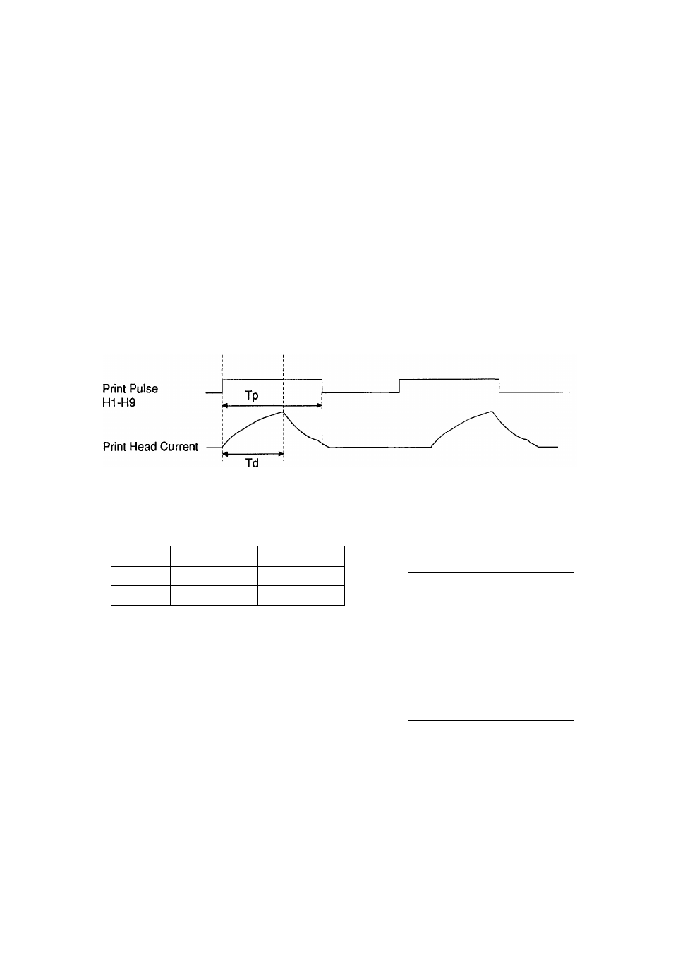
The CPU (IC200) sends the printhead trigger pulses from terminal T04 to the Gate Array. During this time, the
head pin solenoids are fired by Q206-216 according to the data received from the Gate Array as H1-H9. IC205
and Q206, Q207 control the current used to drive the pin solenoids. A thermistor is attached in the printhead
and is used to detect overheating.
Timing Chart
8.2.6 Head Drive Block
Print Data
^
Trigger Pulse
X
Print Pulse
Print Pulse Time
Print Mode
Td
Tp
Draft
about 280 |i sec about 492 p. sec
Bit Image
about 280 sec
about 492 ц sec
Printhead
Pin No.
CN203
Resistance Value
1-5
24.9 ± 0.5 ohms
2-5
24.9 ± 0.5 ohms
3-5
24.9 ± 0.5 ohms
4-5
24.9 ± 0.5 ohms
9-7.8
24.9 ± 0.5 ohms
11-7.8
24.9 ± 0.5 ohms
13-7.8
24.9 ±0.5 ohms
14-7.8
24.9 ± 0.5 ohms
15-7.8
24.9 ± 0.5 ohms
10-12
Less than
37K±8 Kohms (at25t:)
6
OPEN