Panasonic KX-P1150 User Manual
Page 28
Attention! The text in this document has been recognized automatically. To view the original document, you can use the "Original mode".
KX-P1150
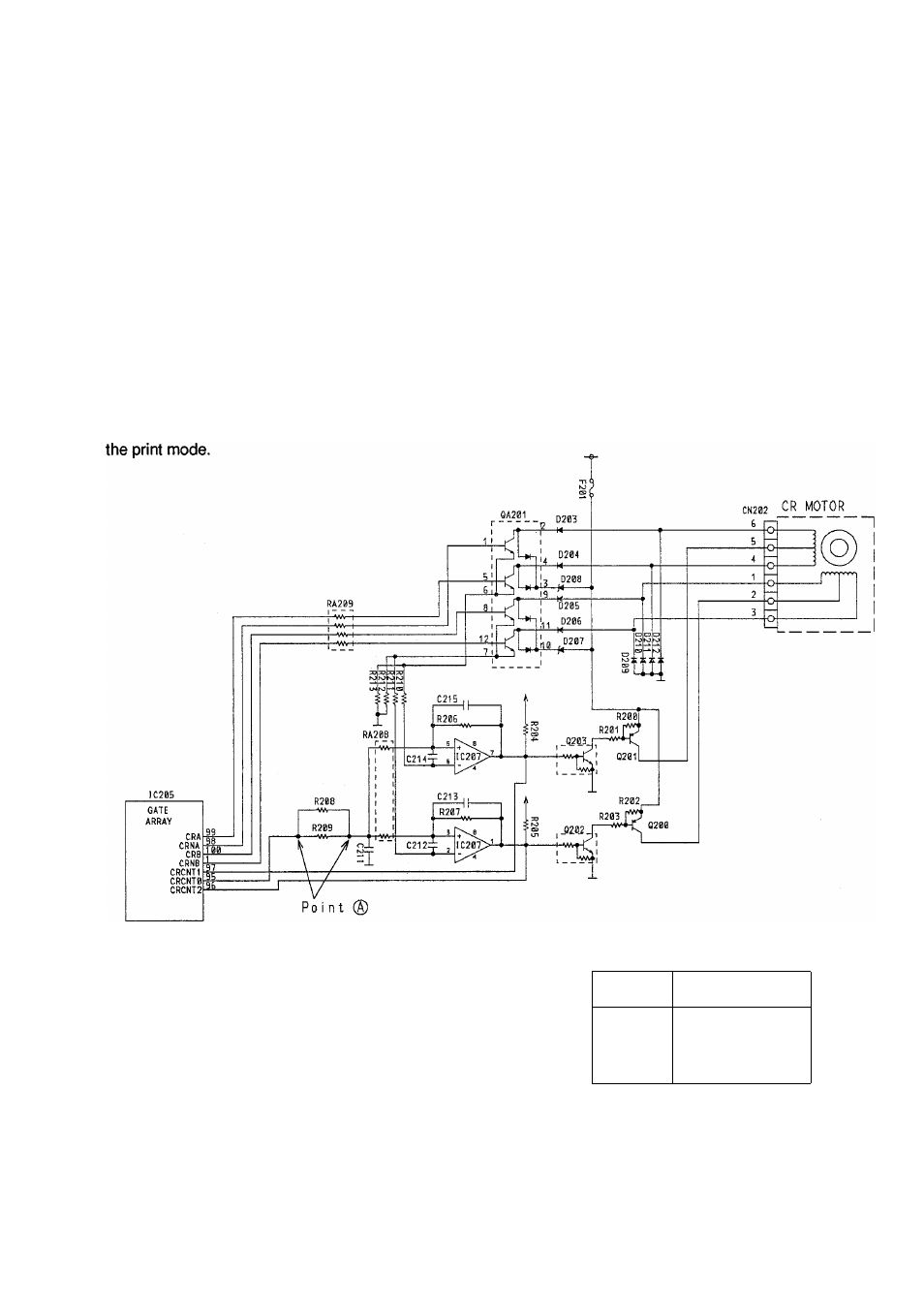
The Carriage motor is driven by the four signals from CRA, CRB, CRNA and CRNB, and is driven by 1-2 phase
driving system.
The time interval is determined by the CPU's interval counter clock as generated from the CPU's clock.
This circuit is a chopper drive circuit for fixing the amount of the current through the motor during stepping and
has two threshold voltages
(V
sh
, V
sl
).
IC207 compares the voltage drop across R212 (R213) which is in
proportion to the current through the motor. For example, when the voltage drop across R212 (R213) is larger
than
V
sh
,
IC207 is turned off and Q202 (Q203) is turned off, then Q200 (Q201) is turned off. At the same time, the
current through the motor decreases, because the voltage drop across R212 (R213) decreases. When this
voltage drop is smaller than
V
sl
,
IC207 is turned on, and the current through the motor increases.
The amount of current through the motor is fixed during stepping by repeating this process.
These threshold voltage
(V
sh
, V
sl
)
are able to be changed by IC205
pin
95 H or L signal duty Ratio according to
8.2.4 Carriage Motor Drive Biock
Timing Chart
CRA
CRB
CRNA
Carriage Motor Coil Resistance Value
Pin No.
(CN202)
Resistance Value
6-5
9.5 ± 0.7 ohms
4-5
9.5 ± 0.7 ohms
1-2
9.5 ± 0.7 ohms
3-2
9.5 ± 0.7 ohms
CRNB