Timing chart, Lfa _ lfb, Lfna – Panasonic KX-P1150 User Manual
Page 29: Lfnb
Attention! The text in this document has been recognized automatically. To view the original document, you can use the "Original mode".
KX-P1150
Pulse Rate Chart
Relation between the printing mode and the pulse rate is shown in the chart.
Printing Mode
Pulse Rate(PPS)
Current Control
CRCNTO OUTPUT PULSE DUTY
Holdinq State
0
20/128
DRAFT
10CPI
1953
10/128
12CPI
1953
10/128
15CPI
1953
10/128
17CPI
977
6/128
20CPI
977
6/128
LQ
10CPI
977
6/128
12CPI
977
6/128
15CPI
651
6/128
17CPI
488
6/128
20CPI
488
6/128
POINT A
b
Note: The CRCNTO Output Pulse Duty Cycle is determined by dividing the on time
of the pulse (b) by the total time of the pulse (a), measured at point A of the
carriage motor drive circuit.
b/a=CRCNTO Output Pulse Duty Cycle
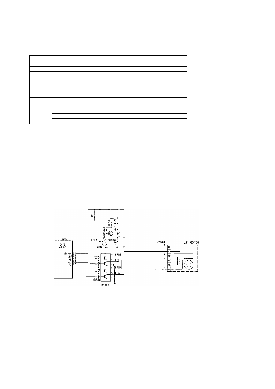
8.2.5 Paper Feed Motor Drive Block
During paper feed, IC205 sets LFEN (pin @ ) at the H level and turns on Q204 and 0205. +39V is then fed to
the motor.
The driving method by LFA, LFNA, LFB, LFNB is a 2-2 driving system and the pulse rate is 400 pulses per
second. When paper feed is not active, 0205 is turned off by LFEN (pin @) L level signal and then a holding
voltage (about 2V) is applied to the motor through R214.
The Line Feed Motor is protected from current overload by setting LFA, LFNA, LFB, LFNB and LFEN to a L
level. This is controlled by the Dip-SW Port of IC205 (pin @ ) detecting the collector voltage of 0205 through
R221-R223 and R260.
R222 R221 R260
Timing Chart
LFA _
LFB
Paper Feed Motor
LFNA
LFNB
Pin No.
(CN203)
Resistance Value
1-2
140 ± 10 ohms
3-2
140 ± 10 ohms
4-5
140 ± 10 ohms
6-5
140 ± 10 ohms