Panasonic KX-P1150 User Manual
Page 21
Attention! The text in this document has been recognized automatically. To view the original document, you can use the "Original mode".
KX-P1150
(c)
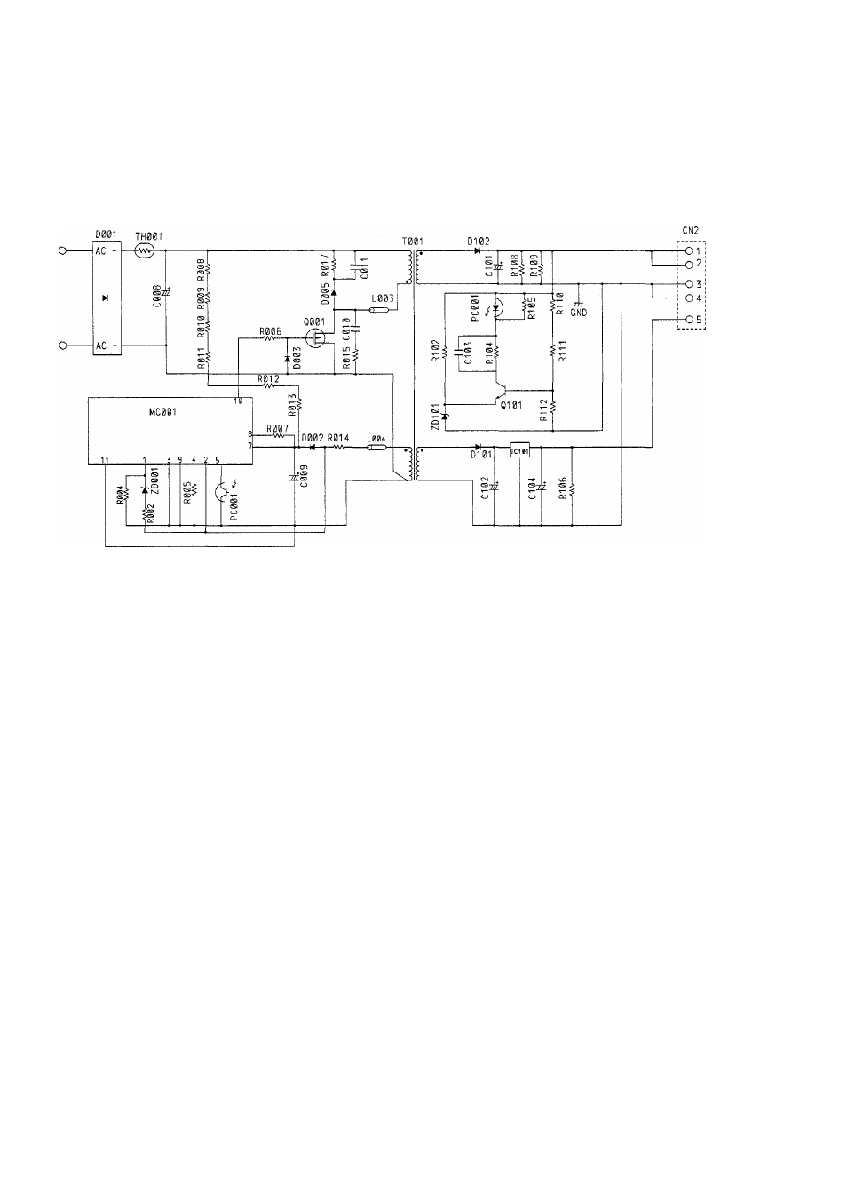
Converter Circuit
This power supply produces 2 output voltages (+36VDC and +5VDC). The output voltages are stabilized
by controlling the on and off period of Transformer T001, which is controlled by MC001 monitoring the
+36VDC output and then turning Q001 on and off. +
8
VDC is input to IC101, a three pin regulator that
regulates the +5VDC output.
+36V
GND
+ BV
(d)
Control Circuit and Error Detection Circuit
When the +36VDC output voltage increases, the current of photocoupler PC001 increases, MC001
monitors this current level and controls on and off time of Q001. The turning on and off of Q001 controls
the oscillation frequency of T001 which regulates the +36VDC output.
(e)
Over Current Limiter
IC101 has built in over current protection and protects the +5VDC circuit from current overload. Control
circuit MC001 provides over current protection for the +36VDC circuit by controlling Q001 turn on time
by an internal limiter circuit.