Carrier 19XR,XRV Hermetic Centrifugal Liquid Chillers User Manual
Page 59
59
VFD Cooling System Leak Inspection
1. Check for leaks on the refrigerant cooling flange connec-
tions to the VFD enclosure.
2. Check for leaks on all tubing internal to the VFD enclo-
sure, the tubing flair connection to the VFD module and
the TXV valve.
3. Verify that the VFD refrigerant cooling system TXV
valve control bulb is securely inserted into the VFD drive
module heat sink.
Power Up Verification
1. Inspect control wiring inside the VFD and verify the in-
tegrity of the connections between the integrated starter
module (ISM) and the VFD module.
2. Close the control power switch in the VFD enclosure.
3. Close the oil pump power switch inside the VFD
enclosure.
4. Verify the VFD disconnect switch is in the open position.
5. Close and latch the doors of the VFD enclosure.
6. Apply power to the VFD enclosure. Remove lock outs
and close all disconnects.
7. Verify that the CVC/ICVC display powers up and goes to
the default screen.
8. Close the VFD disconnect switch.
9. Verify the following actions during the VFD start-up self
test:
• The display shows SELF and all LEDs are illumi-
nated for 5 to 6 seconds.
• The display reads a 0 after the diagnosis is
complete.
• If Err is displayed a fault has been detected.
Perform manual reset by establishing a reset
through the small hole under the VFD Keypad. If
this does not correct the fault contact your Carrier
representative.
• If AR with a counting down number is displayed
wait for the number to count to 0 and the display
should then revert to a 0. If the counter starts over
at 30 contact Carrier representative.
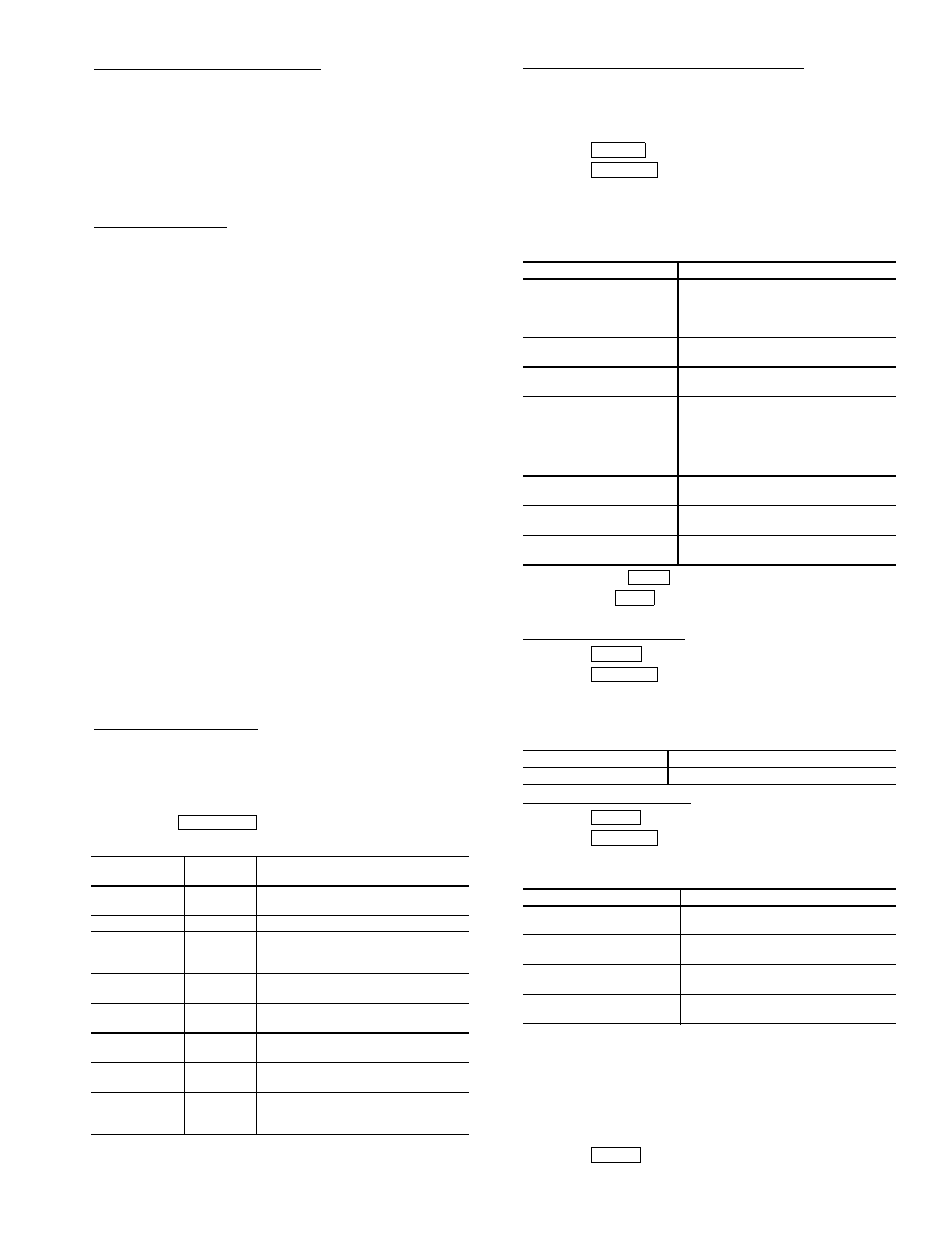
Configure VFD Parameters — The VFD controller must have
job specific parameters set as defined by the component name-
plates and labels. The parameters come preset by the factory,
but must be verified prior to start-up by accessing the PRO-
GRAM MODE of the VFD controller keypad. For information
on how to access the VFD keypad see page 58.
Press the
softkey to access the parameter
screen to modify or view the following job specific parameters:.
Configure Chiller Visual Controller Parameter — The chiller
controller must have its job specific parameters set as defined
by the job sheet or installed nameplates. Below are the job spe-
cific parameters that must be set:
To access the ISM_CONF screen:
1. Press .
2. Press .
3. Enter the password 1111.
4. Select ISM (CONFIG STARTER DATA)
5. Scroll down and select the ISM_CONF DATA screen to
modify or view the ISM parameters:
6. Press to the
softkey to save changes.
7. Press the
softkey to and exit the ISM Configura-
tion Screen.
VFD Enable Configuration — To access the parameters:
1. Press .
2. Press .
3. Select EQUIPMENT SERVICE.
4. Scroll down and select SETUP2.
5. Verify the following parameters:
Configure Surge Parameters
1. Press .
2. Press .
3. Select EQUIPMENT SERVICE and OPTIONS to verify
the following:
VFD CONTROL VERFICATION (Non-Running) — In order
to verify and, if necessary, tune the speed control signal of the
chiller controller to the VFD (ISM terminal J8 1-2 labeled
4-20 mA OUT VFD) and the speed feedback signal from the
VFD to the chiller controller (ISM terminal J6 1-2 labeled
VFD HZ), follow the steps below.
Set TARGET VFD SPEED to 0%.
1. Press .
VFD
PARAMETER
TITLE
SETTING
P.004
Maximum
Speed
Line Frequency selected. Per
Compressor Nameplate.
P.006
Password
107
P.028
Speed
Display
Scaling
60 for 60 Hz selection and
50 for 50 Hz selection
H.000
Motor
Voltage
Compressor nameplate voltage.
H.001
Frequency
Line Frequency selected. Per
Compressor Nameplate.
H.002
Motor
Amps
Compressor nameplate amps.
H.021
Line
Voltage
VFD nameplate voltage.
H.022
Over
Frequency
Limit
69 for 60 Hz selection and
57 for 50 Hz selection.
PROGRAM
DESCRIPTION
SETTING
STARTER TYPE
(2 = SS/VFD)
2
MOTOR RATED
LINE VOLTAGE
VFD Nameplate Voltage.
MOTOR RATED
LOAD AMPS
VFD Nameplate Chiller Rated Load
Amps
MOTOR LOCKED
ROTOR TRIP
Compressor Nameplate
STARTER LRA RATING
600 for VFD
part #19XVR0414XXX
700 for VFD
part #19XVR0500XXX
900 for VFD
part #19XVR0643XXX
MOTOR CURRENT
CT RATIO:1
163
120 (414A)
3 GRND FAULT CT?
(1=NO)
NO
FREQUENCY-60HZ
(NO=50)
NO for 50 Hz selection
YES for 60 Hz selection
VFD OPTION
ENABLED
VFD CURRENT LIMIT
COMPRESSOR NAMEPLATE AMPS
DESCRIPTION
SETTINGS
SURGE/HGBP
DELTA T1
Surge parameter label
SURGE/HGBP
DELTA P1
Surge parameter label
SURGE/HGBP
DELTA T2
Surge parameter label
SURGE/HGBP
DELTA P2
Surge parameter label
ENTER
SERVICE
SAVE
EXIT
MENU
SERVICE
MENU
SERVICE
MENU