Carrier 19XR,XRV Hermetic Centrifugal Liquid Chillers User Manual
Page 57
57
CHANGE THE BENSHAW INC., RediStart MICRO™
SOFTWARE CONFIGURATION IF NECESSARY — Ben-
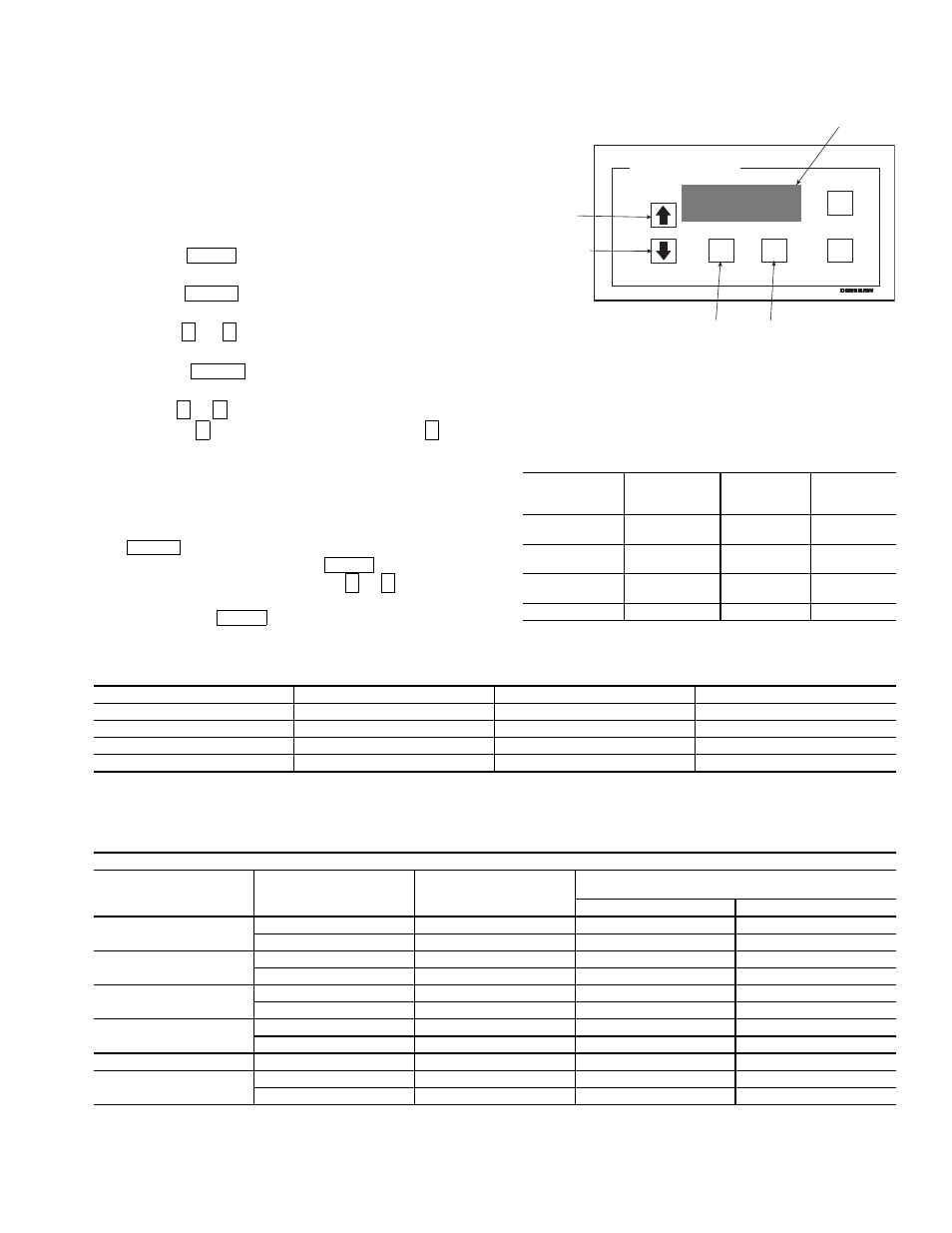
shaw starter configurations are checked and modified from the
menus in the Benshaw Redistart MICRO Default Display. See
Fig. 32 and Table 6 for default display and menu items. To ac-
cess the menus to perform checks and modifications, the Ben-
shaw starter must be powered up and its self-test must have
been successfully completed. The self-test takes place automat-
ically after power-up. Current transformer ratio configurations
and hardware switch settings checks are performed in the
MENU1 display screen. See Table 7 for menu structure and
Table 8 for switch settings.
1. Press the
softkey until the desired menu is se-
lected on the display.
2. Press the
softkey to access the displayed menu
items (Table 6).
3. Use the
or
arrow keys to scroll between menu
items until the desired item is reached on the display.
4. Press the
softkey to access the value to be
changed.
5. Use the
or
arrow keys to adjust the new displayed
value. The
key increases the value while the
key
decreases the value. Holding the arrow key will progres-
sively increase the rate of change. The value will stop
changing when either the factory set minimum or maxi-
mum value is reached. To make fine adjustments press
and release the arrow key.
6. When the correct value has been selected, press the
key to store the new configuration. At this
point, there are two options. The
key will return
the display to the main display. The
or
arrow keys
will move the display to the next menu item. When fin-
ished press the
key to return to the main display.
To view other settings and troubleshooting guide consult the
Benshaw RediStart MICRO instructional manual included in
the starter.
Table 6 — Benshaw RediStart
MICRO Menu Structure
Table 7 — Benshaw RediStart MICRO Menu Items*
*These values are not displayed in the ISM_CONFIG table.
Table 8 — Benshaw RediStart MICRO Current Transformer DIP Switch Settings
LEGEND
CT — Current Transformer
MENU
ENTER
↓
↑
ENTER
↑
↓
↑
↓
ENTER
MENU
↑
↓
MENU
MENU 1
Starter Setup
MENU 2
Meter Setup
MENU 3
Event
Recorder
MENU 4
Dry Run
Mode
Initial Current
as % RLA
Meter #1
display
Events 1-99
Dry Run
Mode
Max. Cur
As% LRA
Meter #2
display
Ramp Time
(sec.)
CT Ratio: 1
DESCRIPTION
RANGE
UNITS
DEFAULT
INITIAL CURRENT
50-300
%
125
MAX. CURR AS % LRA
30-70
%
55
RAMP TIME
5-30
SEC
15
CT RATIO
2640-5760
Enter Value from Table 8.
CURRENT TRANSFORMER CT1-CT3
Starter
Frame Size
(Amps)
Motor
RLA Range
(Amps)
CT
Ratio
MIcro Power Card (BIPCMIPWR-C4)
Overload Switch Settings
SW1-1
SW1-2
200 Amps
95- 135 Amps
3900:1
OFF
OFF
136- 200 Amps
5760:1
OFF
OFF
300 Amps
201- 231 Amps
2640:1
ON
OFF
232- 300 Amps
3900:1
ON
OFF
480 Amps
301- 340 Amps
3900:1
ON
OFF
341- 480 Amps
5760:1
ON
OFF
600 Amps
481- 580 Amps
2640:1
ON
ON
581- 600 Amps
3900:1
ON
ON
740 Amps
601- 740 Amps
3900:1
ON
ON
1250 Amps
741- 855 Amps
3900:1
ON
ON
856-1250 Amps
5760:1
ON
ON
FAULT
RESET
MENU
ENTER
DISPLAY
SCROLL UP
SCROLL DOWN
MENU
SELECTION
MENU ENTRY
DATA ENTRY
STOP I = OA
READY V = 461V
RediStart MICRO
Fig. 32 — Benshaw RediStart
MICRO Default Display