Carrier 19XR,XRV Hermetic Centrifugal Liquid Chillers User Manual
Page 21
21
7. Press
to register the values and to move hori-
zontally (left to right) within a period.
8. Press
to leave the period or override.
9. Either return to Step 4 to select another period or over-
ride, or press
again to leave the current time
schedule screen and save the changes.
10. The Holiday Designation (HOLIDEF table) may be
found in the Service Operation section, page 45. The
month, day, and duration for the holiday must be
assigned. The Broadcast function in the BRODEF
table also must be enabled for holiday periods to
function.
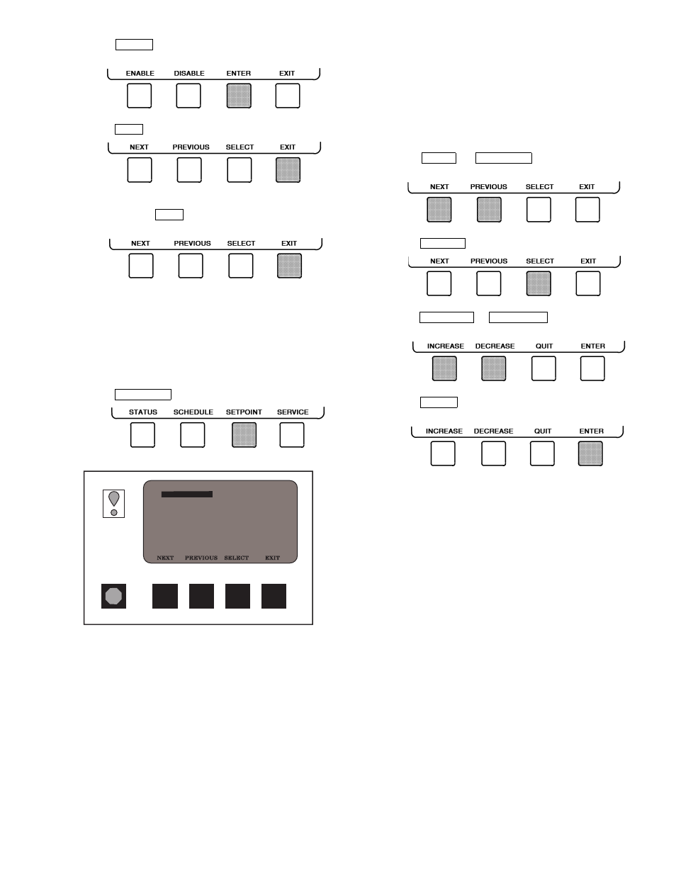
TO VIEW AND CHANGE SET POINTS (Fig. 20)
1. To view the SETPOINT table, from the MENU screen
press .
2. There are 5 set points on this screen: BASE DEMAND
LIMIT, LCW SETPOINT (leaving chilled water set
point), ECW SETPOINT (entering chilled water set
point), ICE BUILD SETPOINT, and TOWER FAN
HIGH SETPOINT. Only one of the chilled water set
points can be active at one time. The set point that is
active is determined from the SERVICE menu. See the
Service Operation section, page 45. The ice build (ICE
BUILD) function is also activated and configured from
the SERVICE menu.
3. Press
or
to highlight the desired
set point entry.
4. Press
to modify the highlighted set point.
5. Press
or
to change the select-
ed set point value.
6. Press
to save the changes and return to the pre-
vious screen.
SERVICE OPERATION — To view the menu-driven pro-
grams available for Service Operation, see Service Operation
section, page 45. For examples of CVC/ICVC display screens,
see Table 2.
ENTER
EXIT
EXIT
SETPOINT
NEXT
PREVIOUS
SELECT
INCREASE
DECREASE
ENTER
19XR_II
SETPOINT SELECT
SETPOINT
Base Demand Limit
Control Point
LCW Setpoint
ECW Setpoint
ICE BUILD Setpoint
Tower Fan High Setpoint
100%
50.0 F
60.0 F
40.0 F
85.0 F
Fig. 20 — Example of Set Point Screen