Function description, Installation, Funktionsbeschreibung – Pilz PNOZ XHCV 0,7/24VDC 2n/o fix User Manual
Page 2: Montage, Description du fonctionnement
- 2 -
Function Description
The relay PNOZ XHCV provides a safety-
oriented interruption of a safety circuit.
When the operating voltage is supplied the
LED "Power" is illuminated.
When the reset circuit S13 - S14 is closed
and the input circuit is opened, relay K3
energises.
• Input circuit closed (e.g. Emergency Stop
Button not activated): Relays K1 and K2
energise via the N/O K3.1 and K3.2 and
latch via K1.1/K2.1. The status indicators
for "CH.1" and "CH.2" illuminate. The
safety contacts (37-38/47-48) are closed.
• Input Circuit is opened (e.g. Emergency
Stop is pressed):
Following the delay-on de-energisation
period, relays K1 and K2 de-energise. The
safety contacts 37-38 and 47-48 opens
and the LED "CH.1" and "CH.2"
extinguish.
The unit may only be reset once the delay-
on-de-energisation period has lapsed and all
E-Stop and safety contacts are closed.
Operating Modes
• Single-channel operation: Input wiring
according to VDE 0113 part 1 and
EN 60204-1, no redundancy in the input
circuit, earth faults are detected in the
emergency stop circuit.
• Two-channel operation: Redundancy in
the input circuit, earth faults in the
Emergency Stop circuit and shorts across
the emergency stop push button are also
detected.
• Automatic reset: Unit is active as soon as
the input circuit is closed.
• Manual reset: Unit is only active when a
reset button (S13-S14) has been pressed.
Automatic reset following a loss/return of
supply voltage is thereby prevented.
• Increase in the number of available
contacts by connection of external
contactors/relays.
Installation
The safety relay must be panel mounted
(min. IP54). There is a notch on the rear of
the unit for DIN-Rail attachment.
Funktionsbeschreibung
Das Schaltgerät PNOZ XHCV dient dem
sicherheitsgerichteten Unterbrechen eines
Sicherheitsstromkreises. Nach Anlegen der
Versorgungsspannung leuchtet die LED
"Power". Bei geschlossenem Startkreis S13-
S14 sowie geöffnetem Eingangskreis geht
Relais K3 in Wirkstellung.
• Eingangskreis geschlossen (z. B. Not-
Halt-Taster nicht betätigt) Relais K1 und
K2 gehen über die Schließer K3.1 und
K3.2 in Wirkstellung und halten sich selbst
über K1.1 bzw. K2.1. Die Statusanzeigen
für "CH.1" und "CH.2" leuchten. Die
Sicherheitskontakte 37-38/47-48 sind
geschlossen.
• Eingangskreis wird geöffnet (z. B. Not-
Halt-Taster betätigt):
Nach Ablauf der fest eingestellten
Verzögerungszeit fallen die Relais K1 und
K2 zurück. Die Sicherheitskontakte 37-38
und 47-48 öffnen und die LED "CH.1" und
"CH.2" erlöschen.
Bevor das Gerät erneut gestartet werden
kann, muss die Verzögerungszeit abgelau-
fen und alle Not-Halt- und Sicherheits-
kontakte müssen wieder geschlossen sein.
Betriebsarten:
• Einkanaliger Betrieb:
Eingangsbeschaltung nach VDE 0113
Teil 1 und EN 60204-1, keine Redundanz
im Eingangskreis, Erdschlüsse im
Tasterkreis werden erkannt.
• Zweikanaliger Betrieb: Redundanter Ein-
gangskreis, Erdschlüsse im Tasterkreis
und Querschlüsse zwischen den Taster-
kontakten werden erkannt.
• Automatischer Start: Gerät ist aktiv, sobald
Eingangskreis geschlossen ist.
• Manueller Start: Gerät ist erst dann aktiv,
wenn ein Starttaster (S13-S14) betätigt
wird. Dadurch ist eine automatischer Start
des Schaltgeräts nach Spannungsausfall
und -wiederkehr ausgeschlossen.
• Kontaktvervielfachung und -verstärkung
durch Anschluss von externen Schützen.
Montage
Das Sicherheitsschaltgerät muss in einen
Description du fonctionnement
Le relais PNOZ XHCV assure de façon
sure, l’ouverture d’un circuit de sécurité.
A la mise sous tension du relais (A1-A2), la
LED "Power" s'allume. Si le circuit de
réarmement S13-S14 est fermé et les
canaux d’entrée ouverts, le relais K3 colle.
• Fermeture des canaux d’entrée T11, T12
& T22 (par ex. AU non actionné) : les
relais K1 et K2 collent par l’intermédiaire
des contacts K3.1 et K3.2 et
s’automaintiennent par K1.1 et K2.1. Les
LEDs "CH.1" et " CH.2" s'allument. Les
contacts de sécurité (37-38/47-48) sont
fermés.
• Circuits d'entrée ouverts (poussoir AU
actionné) :
Au bout de la temporisation affichée, les
relais K1 et K2 retombent. Les contacts de
sécurité 37-38/47-48 s'ouvrent et les LEDs
"CH.1" et "CH.2" s'éteignent.
Les canaux d'entrée doivent être refermés et
la temporisation écoulée avant de pouvoir
réarmer à nouveau le relais.
Modes de fonctionnement
• Commande par 1 canal : conforme aux
prescriptions de la EN 60 204-1, pas de
redondance dans le circuit d’entrée, la
mise à la terre du circuit d’entrée est
détectée
• Commande par 2 canaux: circuit d’entrée
redondant, la mise à la terre et les courts-
circuits entre les contacts sont détectés.
• Réarmement automatique : le relais est
activé dès la fermeture des canaux
d’entrée.
• Réarmement manuel : le relais n’est activé
qu’après une impulsion sur un poussoir de
validation (S13-S14). Un réarmement
automatique du relais après une coupure
d’alimentation est ainsi impossible.
• Augmentation du nombre de contacts ou
du pouvoir de coupure par l’utilisation de
contacteurs externes.
Montage
Le relais doit être monté en armoire ayant un
indice de protection mini IP54. Sa face
arrière permet un montage sur rail DIN.
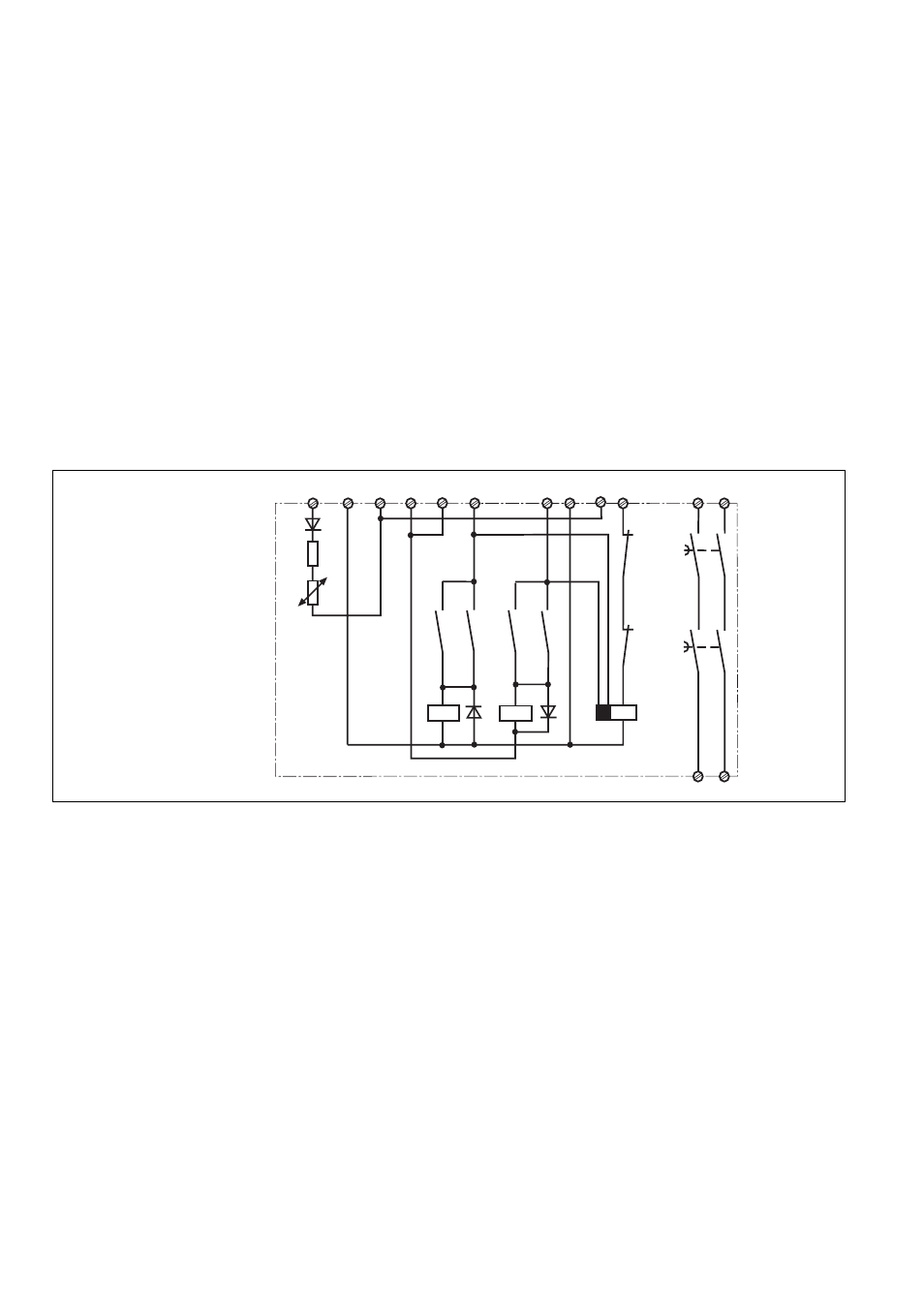
Fig. 1: Innenschaltbild/
Internal Wiring Diagram/
Schéma de principe
K1.1
K3.1
K2.1 K3.2
K1.2
K2.2
K1
K2
K3
A1 (L+) A2 (L-) S11
S12
S32
S22 S21
S14
37
47
38
48
S31
S13
K1
K2
Schaltschrank mit einer Schutzart von mind.
IP54 eingebaut werden. Zur Befestigung auf
einer Normschiene dient ein Rastelement auf
der Rückseite des Geräts.