Pilz PNOZ X7 24VACDC 2n/o User Manual
Page 2
- 2 -
• Bei jedem Ein-Aus-Zyklus der Maschine
wird automatisch überprüft, ob die Relais
der Sicherheitseinrichtung richtig öffnen
und schließen.
Funktionsbeschreibung
Das Schaltgerät dient dem sicherheits-
gerichteten Unterbrechen eines Sicherheits-
stromkreises.
Voraussetzung: Anlegen der Versorgungs-
spannung über den NOT-AUS-Taster,
Brücke zwischen Y1-Y2 oder Starttaster
zwischen Y1 und Y2 betätigt.
• Eingangskreis geschlossen (z. B. NOT-
AUS-Taster nicht betätigt)
Relais K1 und K2 gehen in Wirkstellung
und halten sich selbst. Die Sicherheits-
kontakte 13-14/23-24 sind geschlossen.
• Eingangskreis wird geöffnet (z. B. NOT-
AUS-Taster betätigt)
K1 und K2 fallen in die Ruhestellung
zurück. Die Sicherheitskontakte 13-14/23-
24 werden redundant geöffnet.
Betriebsarten
• Einkanaliger Betrieb:
Eingangsbeschaltung nach VDE 0113
und EN 60204, keine Redundanz im
Eingangskreis. Erdschlüsse im Taster-
kreis werden erkannt.
• Automatischer Start: Gerät ist aktiv,
sobald der Eingangskreis geschlossen ist.
• Manueller Start: Gerät ist erst dann aktiv,
wenn ein Starttaster betätigt wird.
Dadurch ist ein automatischer Start des
Schaltgeräts nach Spannungsausfall und
Spannungswiederkehr ausgeschlossen.
• Kontaktvervielfachung und Kontakt-
verstärkung durch Anschluss von
externen Schützen.
14
24
K2
K1
13
23
~
=
G
A2
A1
A
1
2
Y1
Y2
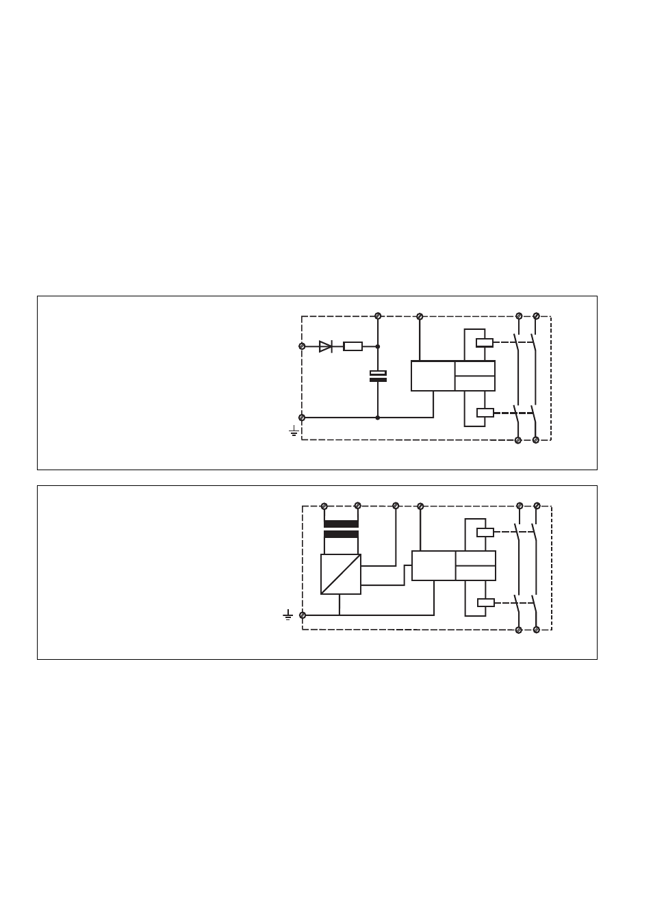
A: Einschaltlogik, zyklischer Test, Steuerlogik/
Operating Logic, Cycle Test, Control Logic/
Logique d'entrée, test cyclique, logique de
commande
1: Kanal 1/Channel 1/Canal 1
2: Kanal 2/Channel 2/Canal 2
Fig. 2: PNOZ X7 AC Schematisches Schaltbild/Connection Diagram/Schéma de principe
A: Einschaltlogik, zyklischer Test, Steuerlogik/
Operating Logic, Cycle Test, Control Logic/
Logique d'entrée, test cyclique, logique de
commande
1: Kanal 1/Channel 1/Canal 1
2: Kanal 2/Channel 2/Canal 2
Fig. 1: PNOZ X7 24 V AC/DC Schematisches Schaltbild/Connection Diagram/Schéma de principe
14
24
K2
K1
13
23
A2
A1
A
1
2
Y1
Y2
+
• The correct opening and closing of the
safety function relays is tested
automatically in each on-off cycle.
Function Description
Operating Modes
• Single-channel operation:
Input wiring according to VDE 0113 and
EN 60204, no redundancy in the input
circuit. Earth faults are detected in the
emergency stop circuit.
• Automatic reset: unit is active, as soon as
the input circuit is closed.
• Manual reset: unit is only active, when a
reset button has been pressed. Automatic
reset following a loss/return of supply
voltage is thereby prevented.
• Increase in the number of contacts
available by connecting external
contactors / relays.
• test cyclique du relais à chaque mise sous
tension de la machine.
Description du fonctionnement
Le bloc logique assure de façon sûre
Mode de fonctionnements
• Commande par 1 canal :
conforme aux prescriptions de la norme
EN 60204, pas de redondance dans le
circuit d'entrée.La mise à la terre du
circuit d'entrée est détectée.
• Réarmement automatique : le relais est
activé dès la fermeture du circuit
d'entrée.
• Réarmement manuel : le relais n'est
activé qu'après une impulsion sur le
poussoir de réarmement. Un réarmement
automatique du relais après une coupure
d'alimentation est ainsi impossible.
• Augmentation du nombre de contacts ou
du pouvoir de coupure par l'utilisation de
contacteurs externes
The relay provides a safety-oriented
interruption of a safety circuit.
Function: apply the operating voltage via the
E-Stop button, link between Y1-Y2 or
activate the reset button between Y1-Y2.
• Input circuit closed (e.g. emergency stop
button not operated):
Relays K1 and K2 energise and latch.
The safety contacts 13-14/23-24 are
closed.
• Input circuit opened (e.g. emergency stop
button operated):
K1 and K2 de-energise. The safety
contacts 13-14/23-24 are opened
redundantly.
l'ouverture d'un circuit de sécurité.
Préalables: tension d'alimentation présente
sur poussoir AU , ponts entre Y1-Y2 ou
poussoir sur Y1-Y2 actionné
• circuit d'entrée fermé (par ex. poussoir
AU non actionné)
Les relais K1 et K2 passe en position
travail et s'auto-maintiennent. Les
contacts de sécurité 13-14/23-24 se
ferment.
• circuit d'entrée ouvert (par ex. poussoir
AU actionné)
K1 et K2 retombent. Les contacts de
sécurité 13-14/23-24 s'ouvrent de façon
redondante.