Funktionsbeschreibung, Function description, Description du fonctionnement – Pilz PNOZ 2VJ 24VDC 3n/o 1n/c 2n/o t User Manual
Page 2
- 2 -
Funktionsbeschreibung
Das Schaltgerät PNOZ 2VJ dient dem
sicherheitsgerichteten Unterbrechen eines
Sicherheitsstromkreises.
Voraussetzungen:
Die Betriebsspannung ist angeschlossen (LED
"Power" leuchtet und die Anschlüsse Y1-Y2,
Y39-Y40 und S33-S34 sind jeweils durch eine
Brücke verbunden.
• Eingangskreis geschlossen (z. B. NOT-
AUS-Taster nicht betätigt)
Alle Relais gehen in Wirkstellung und
halten sich selbst. Alle Statusanzeigen
leuchten. Nach Ablauf der Einschalt-
verzögerung schließen die Sicherheits-
kontakte (13-14/23-24/33-34/57-58/67-68)
und der Hilfskontakt (41-42) öffnet. Die
Statusanzeigen leuchten.
• Eingangskreis wird geöffnet (z. B. NOT-
AUS-Taster betätigt)
K1 und K2 fallen in die Ruhestellung
zurück. Die Sicherheitskontakte (13-14/
23-24/33-34) werden redundant geöffnet
und der Hilfskontakt (41-42) geschlossen.
Die Leuchtdioden "ch.1" und "ch.2" erlö-
schen. Gleichzeitig werden die Verzöge-
rungszeiten t1 und t2 gestartet. Nach
Ablauf der Verzögerungszeit t1 öffnet der
Sicherheitskontakt 57-58 und die beiden
Leuchtdioden t1 erlöschen. Nach Ablauf
der Verzögerungszeit t2 öffnet der
Sicherheitskontakt 67-68 und die beiden
Leuchtdioden t2 erlöschen.
Max. Rückfallverzögerung:
Die verzögerten Sicherheitskontakte öffnen
auch bei Ausfall eines Bauteils spätestens
nach der eingestellten Zeit + 50 ms + 15%
des eingestellten Wertes.
Reset-Funktion:
Der Ablauf der Verzögerungszeiten t1 und t2
kann durch Öffnen der Verbindung zwischen
Y39-Y40 (Öffnerkontakt statt Brücke) vorzei-
tig beendet werden.
Statusanzeige:
• LED "ch.1" leuchtet, wenn Relais K1
angezogen hat.
• LED "ch.2" leuchtet, wenn Relais K2
angezogen hat.
• LED "ch.1 - t1" leuchtet, wenn Relais K4
angezogen hat.
• LED "ch.1 - t2" leuchtet, wenn Relais K5
angezogen hat.
• LED "ch.2 - t1" leuchtet, wenn Relais K6
angezogen hat.
• LED "ch.2 - t2" leuchtet, wenn Relais K7
angezogen hat.
Function Description
The PNOZ 2VJ provides a safety-oriented
interruption of a safety circuit.
Pre-requirements:
The supply voltage is applied (LED „POWER“
is on), the feedback control loop (terminals
Y1-Y2) is closed, terminals Y39-Y40 and
S33-S34 must each form a closed circuit
• Input Circuit closed (e.g. Emergency Stop
Button is not pushed):
- all relays are energized and latched by a
hold contact
- all status indicator LED´s illuminate
- after a short energisation delay safety
contacts 13-14, 23-24, 33-34, 57-58 and
67-68 are closed
- aux. contact 41-42 is opened
- the status indicator LED´s remain
illuminated
• Input Circuit opened (e.g. Emergency Stop
Button is pushed):
- relays K1 and K2 de-energise
- contacts 13-14, 23-24 and 33-34 are
opened redundantly
- aux. contact 41-42 is closed
- status indicator LED´s ch.1 and ch.2 are
no longer illuminated
- simultaneously, delay periods t1 and t2
are started
- after the delay period of t1, safety
contact 57-58 is opened and LED´s t1
are no longer illuminated
- after the delay period of t2, safety
contact 67-68 is opened and LEDs t2 are
no longer illuminated
Max. delay on de-energisation:
Even after a component failure, the delayed
safety contacts open after the set time +
50 ms + 15% of the set value at the latest.
Reset Function:
Delay times t1 and t2 can be terminated
prematurely, by opening the connection
between Y39-Y40.
Status Display
• LED „ch.1“ illuminates, when relay K1 is
energized.
• LED „ch.2“ illuminates, when relay K2 is
energized.
• LED „ch.1“ and „t1“ illuminate, when relay
K4 is energized.
• LED „ch.1“ and „t2“ illuminate, when relay
K5 is energized.
• LED „ch.2“ and „t1“ illuminate, when relay
K6 is energized.
• LED „ch.2“ and „t2“ illuminate, when relay
K7 is energized.
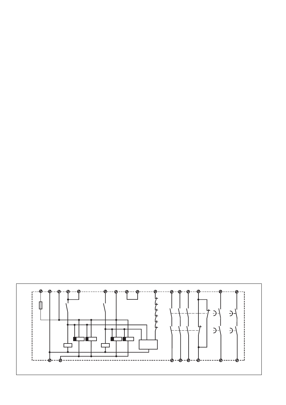
Fig. 1: Schematisches Schaltbild/Principle Wiring Diagram/Schéma de principe
Description du fonctionnement
Le bloc logique PNOZ 2VJ assure de façon
sûre l'ouverture d'un circuit de sécurité.
Préalables:
la tension d'alimentation est présente (LED
"Power" allumée) et ponts entre Y1-Y2,
Y39-Y40 et S33-S34.
• circuit d'entrée fermé (par ex. poussoir AU
non actionné):
Tous les relais internes collent et s'auto-
maintiennent. Toutes les LEDs de
visualisation sont allumées. Après le
temps de réarmement, les contacts de
sécurité (13-14/23-24/33-34/57-58/67-68)
se ferment, le contact d'info. (41-42)
s'ouvre.
• circuit d'entrée s'ouvre (par ex. poussoir
AU actionné):
K1 et K2 retombent. Les contacts de
sécurité (13-14/23-24/33-34) s'ouvrent de
façon redondante et le contact d'info. (41-
42) se ferme. Les LEDs "ch.1" et "ch.2"
sont éteintes. Simultanément les
temporisations t1 et t2 débutent. Au bout
du temps t1, le contact de sécurité 57-58
s'ouvre et les 2 LEDs t1 s'éteingnent. Au
bout du temps t2, le contact de sécurité
67-68 s'ouvre et les 2 LEDs t2
s'éteingnent.
Temps de retombée max:
En cas de défaillance d’un composant
interne, les contacts temporisés s’ouvrent au
bout du temps max. de 50 ms après le
temps défini + 15 % de la valeur réglée.
Fonction Reset:
L'écoulement des temporisations t1 et t2
peut être interrompu prématurément en
ouvrant le circuit Y39-Y40 (câblage d'un
contact à ouverture à la place du pont).
Leds de visualisation
• LED „ch.1“ s'allume, quand le relais K1
est monté.
• LED „ch.2“ s'allume, quand le relais K2
est monté.
• LED „ch.1“ et „t1“ s'allument, quand le
relais K4 est monté.
• LED „ch.1“ et „t2“ s'allument, quand le
relais K5 est monté.
• LED „ch.2“ et „t1“ s'allument, quand le
relais K6 est monté.
• LED „ch.2“ et „t2“ s'allument, quand le
relais K7 est monté.
Y1
K1
K5
K4
13
23
33
41
14
24
42
K2
K1
Y2
K1
K2
57
58
K5
K4
67
68
K7
K6
S11
S33
S12
S12
A2 (0V)
A1
Y40
K2
K2
K6
K7
t2
t1
S34
34
Y39
S22
(-24V)
K4
K6
K5
K7
K1
Start
Fail Safe
- PNOZ m EF 2MM S1IM 230-240VAC IM 0.01-15 A S1IM 110-127VAC IM 0.01-15 A S1IM 24VDC IM 0.01-15 A UP S1IM 42-48VAC IM 0.01-15 A S1IM 24VAC IM 0.01-15 A S1IM 24VDC IM 0.01-15 A PNOZ 1 24VDC 3n/o 1n/c PNOZ 1 230-240VAC 3n/o 1n/c PNOZ 1 110-120VAC 3n/o 1n/c PNOZ 1 48VAC 3n/o 1n/c PNOZ 1 24VAC 3n/o 1n/c PSEN 2.1p-21/8mm/LED/1switch PSEN 2.1p-20/8mm/1switch PSEN 2.2-20 / 1 actuator PSEN 2.1-10 / 1 actuator PSEN 2.1p-21/PSEN 2.1-20 /8mm/LED/1unit PSEN 2.1p-20/PSEN 2.1-20 /8mm/1unit PSEN 1.2-20 / 1 actuator PSEN 1.1-20 / 1 actuator PSEN 1.1-10 / 1 actuator PSEN 2.1b-20/8mm/10m/ 1switch PSEN 2.1a-20/8mm/5m /1switch PSEN 2.1b-20/PSEN 2.1-20 /8mm/10m/1unit PSEN 2.1a-20/PSEN 2.1-20/8mm /5m/1unit