Block diagram/terminal configuration, Function description, Installation – Pilz PNOZ s7.1 C 24VDC 3 n/o 1 n/c cascade User Manual
Page 4
PNOZ s7.1
Operating Manual PNOZ s7.1
21865-EN-08
4
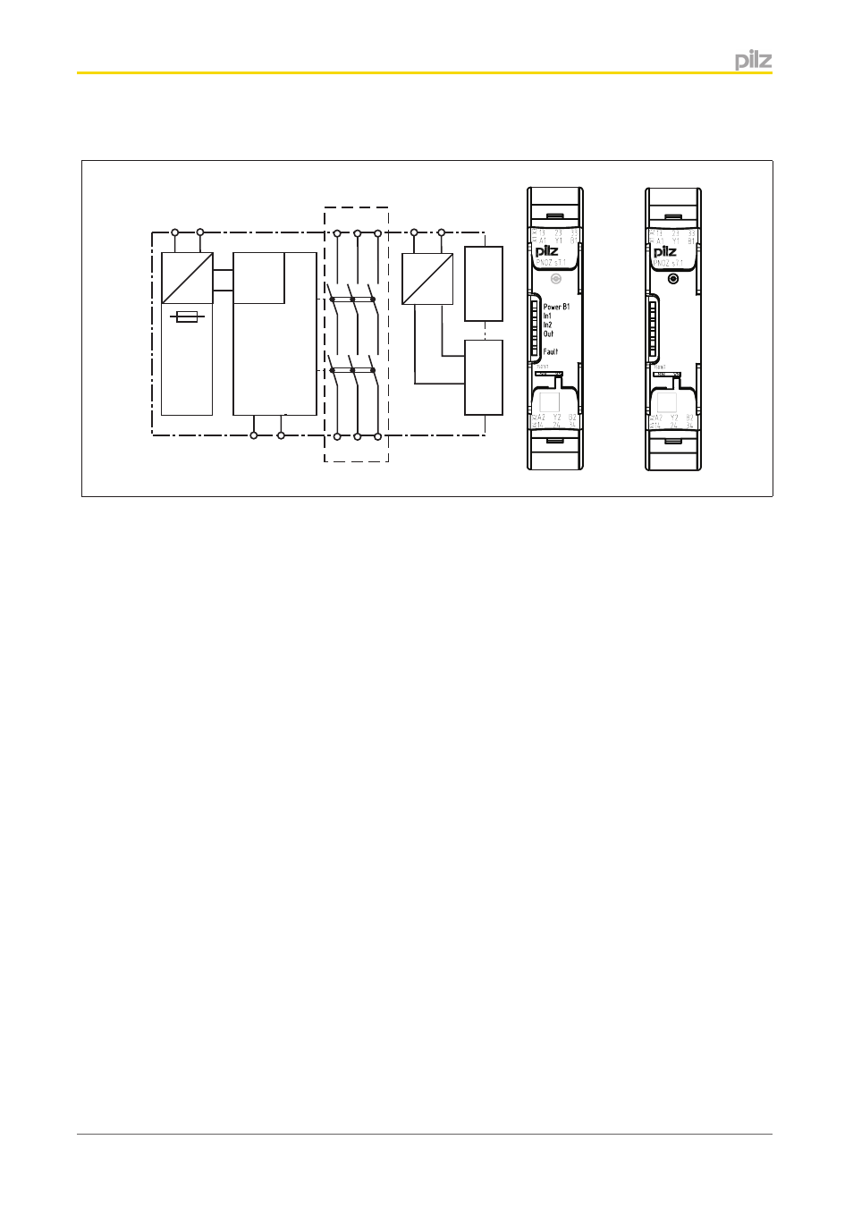
Block diagram/terminal configuration
Input
A1 A2
=
Power
=
K1
K2
13 23 33
Y1
24 34
Y2
14
Interface expansion module
*
B1
B2
Interface
base unit
=
=
Centre: Front view with cover, right: Front view without cover
*Safe separation in accordance with EN 60947-1, 6 kV
Function description
with PNOZsigma base unit:
}
Dual-channel operation via PNOZsigma connector
without PNOZsigma base unit:
}
Single-channel operation: one input circuit affects the output relays
with PNOZsigma s7.2 expander units:
}
Dual-channel operation and supply voltage via PNOZsigma connector
Installation
Install contact expansion module without base unit:
}
Ensure that the plug terminator is inserted at the side of the unit.
Connect base unit and contact expansion module PNOZ s7.1:
}
Remove the plug terminator at the side of the base unit and at the left of the contact ex-
pansion module
}
Connect the base unit and the contact expansion module using the connector supplied,
before mounting the units to the DIN rail.
Connect contact expansion module PNOZ s7.1 to PNOZsigma contact expansion
modules
}
Connect the contact expansion modules using the connector supplied.