Schnittstelle montieren, Gerät in betrieb nehmen, Installing the interface – Pilz PSEN i1 Interface for 4 PSEN 2 User Manual
Page 3: Commissioning the unit, Montage de l'interface, Mise en oeuvre
- 3 -
Schnittstelle montieren
Achtung! Montieren Sie das Gerät in
einen Schaltschrank mit einer
Schutzart von mindestens IP54.
• Befestigen Sie das Gerät mit Hilfe des
Rastelements auf der Rückseite auf einer
Normschiene.
• Sichern Sie das Gerät auf einer senk-
rechten Tragschiene (35 mm) durch ein
Halteelement (z. B. Endhalter oder
Endwinkel)
Gerät in Betrieb nehmen
Betriebsbereitschaft herstellen
PNOZ e3.1p oder PNOZ e3vp und
PNOZ e5.13p:
• Verbinden Sie das PSEN i1 mit einem der
genannten Schutztürwächter.
• Legen Sie bei dem Schutztürwächter die
Betriebsart (z. B. mit/ohne Querschlusser-
kennung) durch Verdrahten des Ein-
gangskreises fest.
Betriebsbereitschaft herstellen
Sicherheitssteuerung der Systemfamilie
PSS und PNOZmulti:
• Verbinden Sie das PSEN i1 mit
- den Eingängen (kompakte PSS oder
PNOZmulti)
- den Eingängen der zentralen Eingabe-
baugruppe (modulare PSS)
- den Eingängen der dezentralen
Eingabebaugruppe (SafetyBUS p)
• Verwenden Sie die Taktausgänge zur
Querschlusserkennung.
S11
S12
S23
S24
1
2
3
4
Y4
S23
PSEN i1
PNOZ e3.1p
PNOZ e3vp
1
2
3
4
A1
S12
S24
Y4
S11
PSEN i1
PNOZ e3.1p
PNOZ e3vp
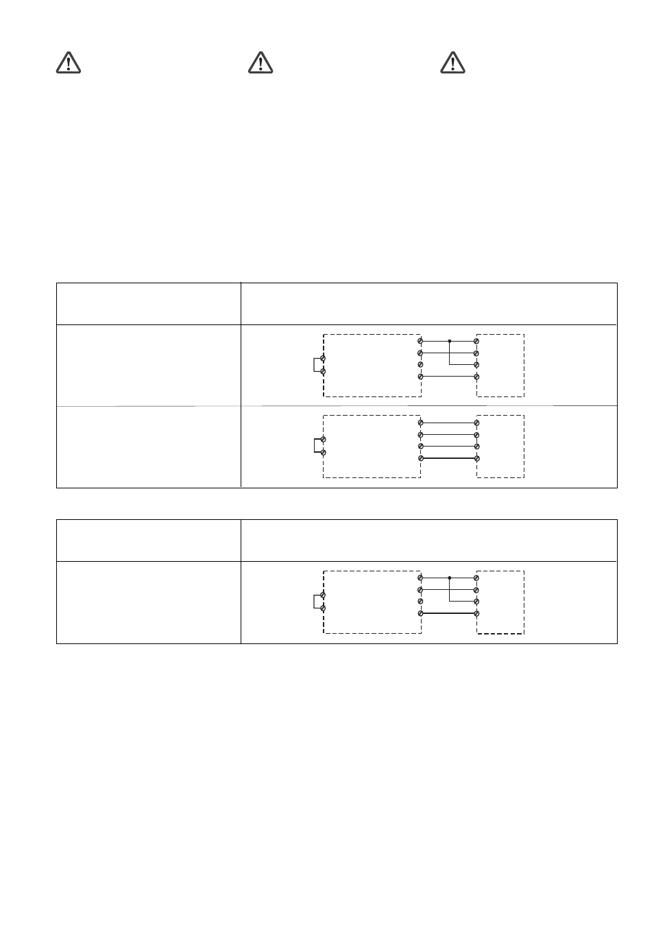
Eingangskreis PNOZ e3.1/PNOZ e3vp
Input circuit PNOZ e3.1/PNOZ e3vp
Circuit d’entrée PNOZ e3.1/PNOZ e3vp
Zweikanalig
Dual-channel
Commande par 2 canaux
ohne Querschlusserkennung
without detection of shorts across contacts
sans détection des courts-circuits
mit Querschlusserkennung
with detection of shorts across contacts
avec détection des courts-circuits
Installing the interface
Caution!The unit should be installed
in a control cabinet with a protection
type of at least IP54.
• Use the notch on the back of the unit to
attach it to a DIN rail.
• Secure the unit on a vertical DIN rail (35
mm) using a retaining bracket or end angle
Commissioning the unit
Preparing for operation
PNOZ e3.1p or PNOZ e3vp and
PNOZ e5.13p:
• Connect the PSEN i1 to one of the named
safety gate monitors.
• Establish the operating mode on the safety
gate monitor (e.g. with/without detection of
shorts across contacts) through the wiring
of the input circuit.
Preparing for operation
Programmable safety system from the
PSS-range and PNOZmulti:
• Connect the PSEN i1 to
- the inputs (compact PSS or PNOZmulti)
- the inputs on the centralised input
module (modular PSS)
- the inputs on the decentralised input
module (SafetyBUS p)
• Use the test pulse outputs to detect shorts
across the contacts.
Montage de l'interface
Attention ! Installez l'appareil dans
une armoire électrique ayant un
indice de protection minimum IP 54.
• Montez l'appareil sur un rail DIN à l'aide du
système de fixation situé au dos du relais.
• Fixez l'appareil sur un rail DIN vertical (35
mm) avec un élément de maintien comme
par ex. un support ou une équerre
terminale.
Mise en oeuvre
Mise en service en liaison avec
PNOZ e3.1p ou PNOZ e3vp et
PNOZ e5.13p :
• Reliez le PSEN i1 avec un des relais
électroniques ci-dessus.
• Définissez par câblage du circuit d'entrée
du relais de contrôle le mode de fonction-
nement souhaité (par ex. avec ou sans
détection de courts-circuits).
Mise en service en liaison avec
automates de sécurité PSS et PNOZmulti :
• Reliez le PSEN i1 avec
- les entrées de l'automate (PSS compact
ou PNOZmulti)
- les entrées de la carte centrale de
l'automate (PSS modulaire)
- les entrées du module décentralisé
(SafetyBUS p)
• Utilisez les sorties impulsionnelles pour la
détection des courts-circuits.
1
2
3
4
A1
S32
S44
Y37
Y36
PSEN i1
PNOZ e5.13p
Eingangskreis PNOZ e5.13p
Input circuit PNOZ e5.13p
Circuit d’entrée PNOZ e5.13p
Zweikanalig
Dual-channel
Commande par 2 canaux
ohne Querschlusserkennung
without detection of shorts across contacts
sans détection des courts-circuits