Zulassungen gerätebeschreibung, Funktionsbeschreibung, Approvals unit description – Pilz PSEN i1 Interface for 4 PSEN 2 User Manual
Page 2: Function description, Homologations description de l'appareil, Description du fonctionnement
- 2 -
Zulassungen
Gerätebeschreibung
Gerätemerkmale:
• Anschlussmöglichkeit für max. 4 Sicher-
heitssensoren der Serie PSEN 2 oder
max. 4 Positionsschalter mit Öffner-/
Schließer-Kombination
• Statusanzeigen für den Schaltzustand der
Öffnerkreise der angeschlossenen
Sensoren
• 4 Diagnoseausgänge zur Anzeige oder
Auswertung des Schaltzustands der
Öffnerkreise über externe LEDs oder eine
Steuerung
Funktionsbeschreibung
Das PSEN i1 schaltet die 4 Öffnerkreise der
angeschlossenen Sicherheitssensoren/
Positionsschalter parallel und die 4
Schließerkreise in Reihe. Eine Statusanzeige
leuchtet bei geschlossenem Schließerkreis.
Bei Verwendung
• von PNOZ e3.1p, PNOZ e3vp und
PNOZ e5.13p lassen sich durch Serien-
schaltung max. 16 Sicherheitssensoren/
Positionsschalter an 4 PSEN i1 anschlie-
ßen.
• einer kompakten Sicherheitssteuerung der
Systemfamilie PSS, einer modularen
Sicherheitssteuerung der Systemfamilie
PSS mit zentraler Eingabebaugruppe oder
einer SafetyBUS p-fähigen PSS mit
dezentraler Eingabebaugruppe lassen sich
durch Serienschaltung max. 6 Sicherheits-
sensoren/Positionsschalter an 2 PSEN i1
anschließen.
• von PNOZmulti lassen sich durch Serien-
schaltung max. 6 Sicherheitsschalter/
Positionsschalter an 2 PSEN i1
anschließen.
Approvals
Unit description
Unit features:
• Connection for max. 4 safety sensors from
the PSEN 2 series or max. 4 position
switches with N/C / N/O combination
• Status indicators for the switch status of
the N/C circuits of the connected sensors
• 4 diagnostic outputs to display or evaluate
the switch status of the N/C circuits via
external LEDs or a PLC
Function description
The PSEN i1 switches the 4 N/C circuits of
the connected safety sensors/position
switches in parallel and the 4 N/O circuits in
series. A status indicator lights when the
N/O circuit is closed.
When using
• PNOZ e3.1p, PNOZ e3vp and
PNOZ e5.13vp a max. 16 safety sensors/
position switches can be connected to 4
PSEN i1 by linking in series.
• a compact programmable safety system
from the PSS-range, a modular
programmable safety system of the
PSS-range with centralised input module
or a SafetyBUS p-compatible PSS with
decentralised input module, a max. 6
safety sensors/position switches can be
connected to 2 PSEN i1 by linking in
series.
• PNOZmulti a max. 6 safety sensors/
position switches can be connected to 2
PSEN i1 by linking in series.
Homologations
Description de l'appareil
Particularités :
• Possibilité de raccordement de max. 4
capteurs de sécurité PSEN 2 ou de max.
4 interrupteurs de position avec contacts
O/F
• Leds de visualisation des circuits d'ouver-
ture des capteurs raccordés
• 4 sorties statiques d'information pour la
gestion par voyant externe ou API des
capteurs raccordés.
Description du fonctionnement
Le PSEN i1 met en parallèle les 4 contacts à
ouverture des capteurs de sécurité/
interrupteurs de position raccordés et en
série leur contact à fermeture. Une led de
visualisation permet de signaler l'état de
chaque capteur.
En cas d'utilisation
• avec PNOZ e3.1p, PNOZ e3vp et
PNOZ e5.13vp, la mise en série de max.
16 capteurs de sécurité/interrupteurs de
position via 4 PSEN i1 est possible.
• avec un automate de sécurité de la
gamme PSS, un automate modulaire de la
gamme PSS avec cartes centralisées ou
modules déportés via SafetyBUS p, la
mise en série de max. 6 capteurs de
sécurité/interrupteurs de position via 2
PSEN i1 est possible.
• avec un PNOZmulti, la mise en série de
max. 6 capteurs de sécurité/interrupteurs
de position via 2 PSEN i1 est possible.
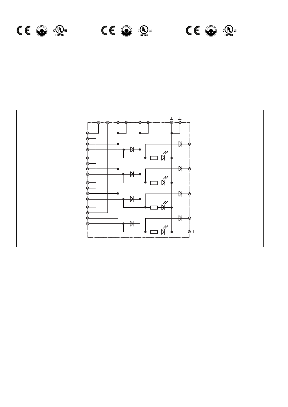
Innenschaltbild
Internal wiring diagram
Schéma interne
2
1
11
12
13
14
21
22
23
24
31
32
33
34
41
42
43
44
3
3
4
4
Y1
Y2
Y3
Y4
S1
S2
S3
S4