Pilz PSEN ma1.3p-22/PSEN ma1.3-12/12mm/ix1/1u User Manual
Page 3
- 3 -
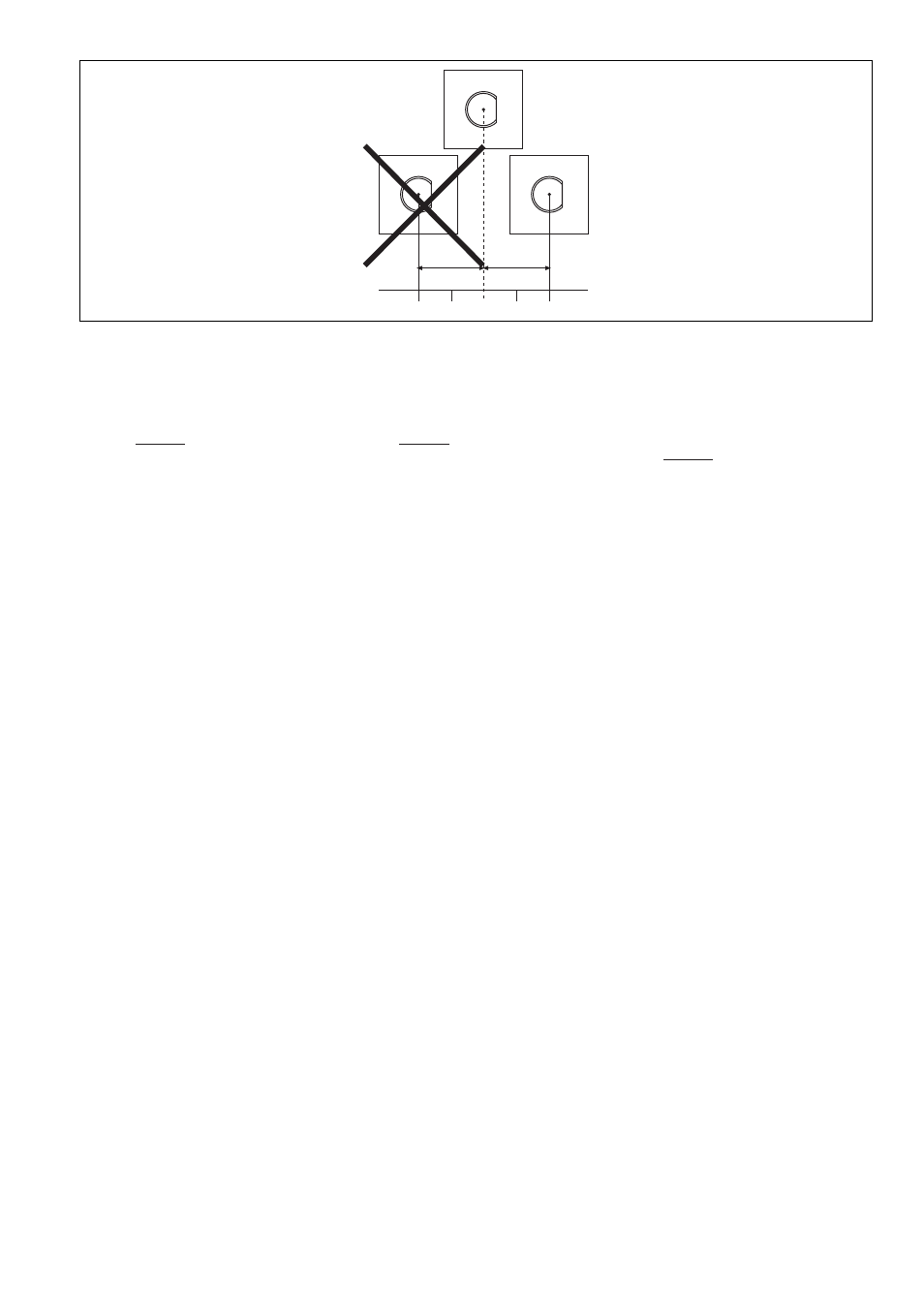
Höhenversatz negativ/positiv
Negative/positive vertical offset
Décalage en hauteur négatif / positif
Verdrahtung
492354955
Beachten Sie:
`
Angaben im Abschnitt „Technische Daten“
unbedingt einhalten.
`
Berechnung der max. Leitungslänge I
max
im
Eingangskreis:
R
lmax
= max. Gesamtleitungswiderstand
(s. techn. Daten)
R
l
/ km = Leitungswiderstand/km
`
Beachten Sie bei Einsatz von Auswertegerä-
ten mit rückfallverzögerten Kontakten:
– Verzögerungszeit
≤
30 s: die rückfallverzö-
gerten Kontakte genügen den Anforderun-
gen der Kategorie 3 gemäß EN 954-1 bzw.
den Anforderungen an PDF mit Einfehlersi-
cherheit (PDF-S).
– Verzögerungszeit
≥
30 s: die rückfallverzö-
gerten Kontakte genügen den Anforderun-
gen der Kategorie 1 gemäß EN 954-1 bzw.
den Anforderungen an PDF mit Zuverläs-
sigkeit durch besonderes Design (PDF-D).
`
Überprüfen Sie in folgenden Fällen von Inbe-
triebnahme die Funktion Querschlusserken-
nung:
– Bei Auswertegeräten mit Versorgungs-
spannung DC: Gesamtleitungswiderstand
≥
15 Ohm pro Kanal
– Bei Auswertegeräten mit Versorgungs-
spannung AC: Gesamtleitungswiderstand
≥
25 Ohm pro Kanal
– Wie Sie die Querschlussprüfung durchfüh-
ren müssen, entnehmen Sie der entspre-
chenden Bedienungsanleitung des
Auswertegeräts.
Wiring
Please note:
`
Information given in the “Technical details”
must be followed.
`
Calculation of the max. cable runs l
max
in the
input circuit:
R
lmax
= max. overall cable resistance (see
Technical details)
R
l
/ km = cable resistance/km
`
When using evaluation devices with delay-on
de-energisation contacts, please note:
– Delay time
≤
30 s: Delay-on de-energisation
contacts satisfy the requirements of cate-
gory 3 in accordance with EN 954-1 and
the requirements of a PDF with single-fault
tolerance (PDF-S).
– Delay time
≥
30 s: Delay-on de-energisa-
tion contacts satisfy the requirements of
Category 1 in accordance with EN 954-1
and the requirements of a PDF with de-
signed reliability (PDF-D).
`
In the following commissioning cases, check
the function that detects shorts across con-
tacts:
– On evaluation devices with DC supply
voltage: Overall cable resistance
≥
15
Ohms per channel
– On evaluation devices with AC supply volt-
age: Overall cable resistance
≥
25 Ohms
per channel
– For details of how to perform the test for
shorts across the contacts, please refer to
the operating manual for the relevant eval-
uation device.
Câblage
Important :
`
Tenez compte impérativement des données
indiquées au chapitre "Caractéristiques
techniques".
`
Calcul de la longueur de câble max. I
max
sur
le circuit d'entrée :
R
lmax
= résistance max. de l'ensemble du
câblage (voir les caractéristiques techni-
ques)
R
l
/km = résistance du câblage/km
`
En cas de mise en œuvre d'appareils de con-
trôle avec contacts temporisés à la retom-
bée, il faut tenir compte des indications
suivantes :
– Temporisation
≤
30 s : les contacts tempo-
risés à la retombée satisfont aux prescrip-
tions de la catégorie 3 selon l'EN 954-1, et/
ou aux prescriptions des PDF avec sécuri-
té de défaut unique (PDF-S).
– Temporisation
≥
30 s : les contacts tempo-
risés à la retombée satisfont aux prescrip-
tions de la catégorie 1 selon l'EN 954-1, et/
ou aux prescriptions des PDF avec une
fiabilité obtenue grâce à un design particu-
lier (PDF-D).
`
Vérifiez dans les cas suivants de mise en ser-
vice la fonction de détection des courts-
circuits :
– pour les appareils de contrôle avec ali-
mentation DC : Résistance de l'ensemble
du câblage
≥
15 ohms par canal
– pour les appareils de contrôle avec ali-
mentation AC : Résistance de l'ensemble
du câblage
≥
25 ohms par canal
– vous trouverez dans la notice d'utilisation
de l'appareil de contrôle comment exécu-
ter le contrôle des courts-circuits.
-2
2
1
0
-1
-
+
R
lmax
R
l
/ km
I
max
=
R
lmax
R
l
/ km
I
max
=
R
lmax
R
l
/ km
I
max
=