Warning, La-z-time, Powerrecline – La-Z-Boy Power Recline after 12/31/2012 User Manual
Page 10: Motion-modulars assembly instructions la-z-time, Motion-modulars assembly instructions
La-Z-Time
®
PowerRecline
+
Motion-Modulars
Assembly Instructions
La-Z-Time
®
PowerRecline
+
Motion-Modulars
Assembly Instructions
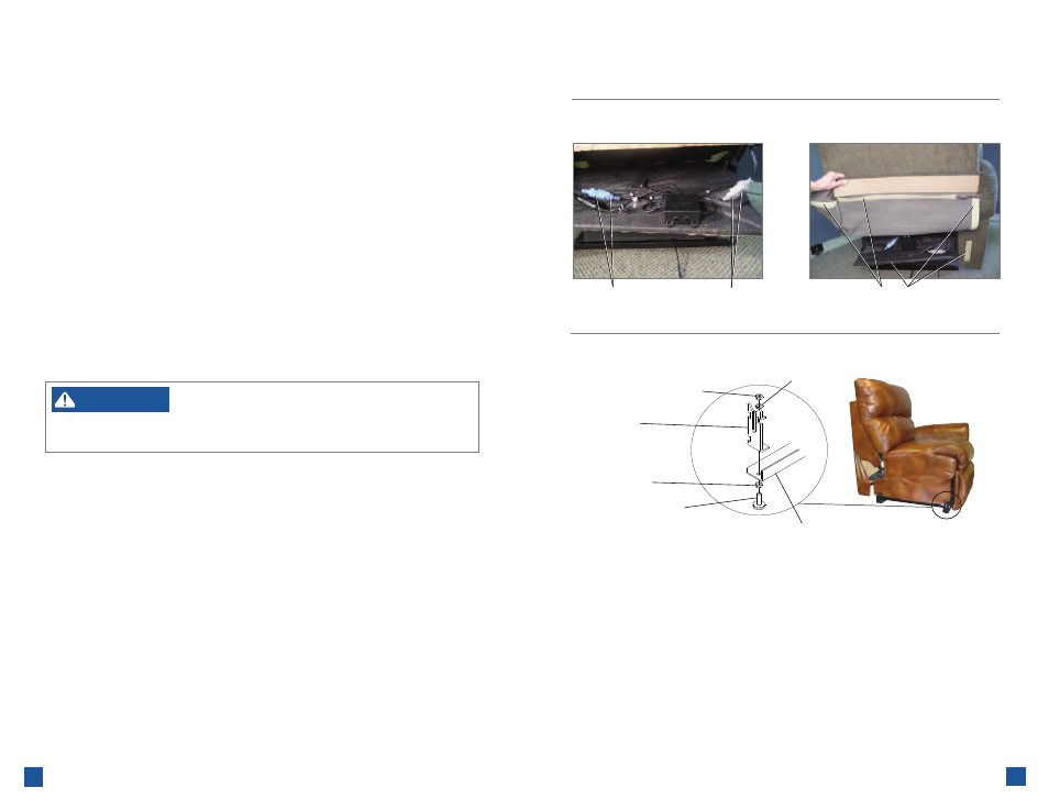
5. Make electrical connections between the back and the body.
•
Locate and identify the two electrical connections between the back and the body.
- The blue connectors on the left side (sitting) are for the adjustable headrest feature. One connector
routes from the bottom of the back and the other from the junction box.
- The gray connectors on the right side (sitting) are for the adjustable lumbar feature. One connector
routes from the bottom of the back and the other from the junction box.
•
Connect the adjustable headrest cables (F
IGURE
7). Align the pins and sockets in the blue
connectors, push the connectors together and close the locking cover to secure the connection.
•
Connect the adjustable lumbar cables (F
IGURE
7). Align the pins and sockets in the gray connectors,
push the connectors together and close the locking cover to secure the connection.
6. Attach the outside back upholstery cover.
•
Locate the fastening tape on the outside back upholstery cover and the fastening tape on the side(s)
and bottom of the rear body rail (F
IGURE
8); location of fastening tape varies by style.
•
Pull the outside back upholstery cover down tight and firmly press the fastening tape on the outside
back upholstery cover to the fastening tape on the body.
7. Choose a location for the power motion-modular unit that is close to an electrical outlet.
– To reduce the risk of injury:
• Provide a clear path for operation of the back and legrest. Place tables and area rugs
at a distance to allow the legrest to fully extend without rubbing or interference.
WARNING
8. Adjustable glides are standard on units with metal base rails. Adjust the glides to a height that provides
an unobstructed path for operation of the legrest (see Furniture Placement Guide).
•
Each glide is attached to the base rail by one jam nut and one lock washer on top of the front
attachment bracket, and one jam nut on the bottom of the base rail (F
IGURE
9, Motion-Modular unit
featured). Loosen the jam nut located on top of the front attachment bracket.
•
Holding the top jam nut, turn the glide clockwise to lower the unit or counterclockwise to
raise the unit.
•
Tighten the bottom jam nut to the base rail, then tighten the top jam nut to the lock washer on top
of the front attachment bracket. Make sure both jam nuts are tight to prevent the bracket from
rotating on the base rail.
•
Repeat this step for each adjustable glide, if necessary.
(PowerRecline
+
Motion-Modulars Assembly Instructions Continued)
F
IGURE
7
F
IGURE
8
F
IGURE
9
Fastening Tape
Adjustable Lumbar
Connection (Gray)
Adjustable Headrest
Connection (Blue)
Upper Jam Nut
Lock Washer
Front
Attachment
Bracket
Lower
Jam Nut
Adjustable
Glide
Base Rail
19
18