Technical data – Kontron KISS 2U X9SCM Low profile User Manual
Page 45
12. Technical Data
KISS 2U V2 – User's Guide (Version 1.00)
12.
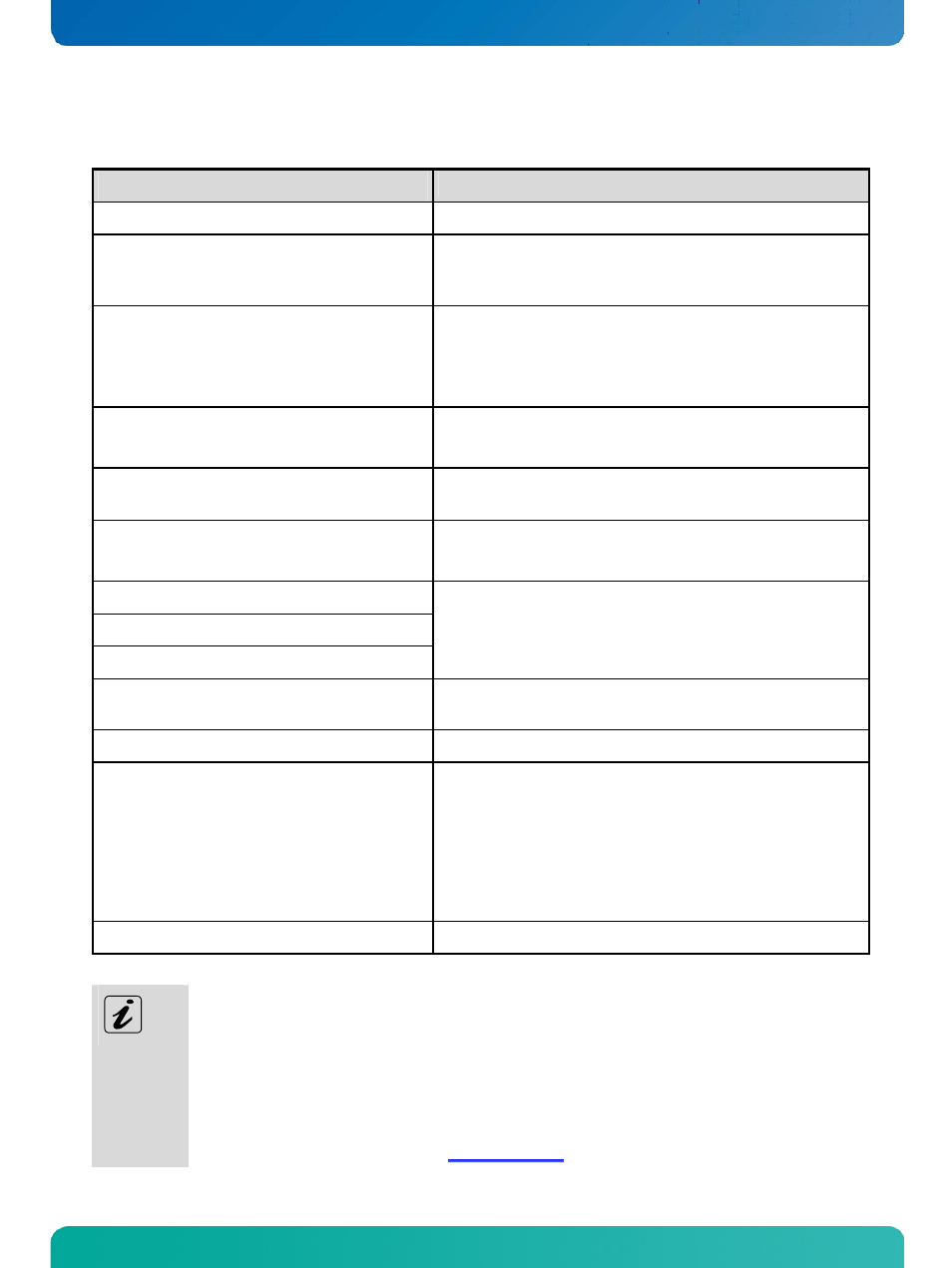
Technical Data
KISS 2U V2-xxxxxxxx-y
Installed CPU Card
* Refer to „KISS 2U V2 System - Configuration Guide“
Controls and Indicators
(at the front side)
Power button
Power LED (green)
HDD LED (orange)
Operating Elements
(at the rear side)
1x ON/OFF switch of the PSU: for system configuration with +24VDC
or -48VDC PSU
1x N/OFF switch of the PSU: for system configuration with
AC wide range PSU (doesn’t disconnect the unit from the mains)
Indicators
(at the rear side)
2x Power LED (green) of the redundant PSU
1x Alarm LED (red) of the redundant PSU
Interfaces
(at the front side)
2x USB (2.0)
Interfaces
(at the rear side)
I/O of the installed CPU card (motherboard/SBC)
* refer to the manual of the installed CPU card (motherboard/SBC)
Drive Bays
Up to two drive bays
* optionally equipped (depending on the system configuration
ordered (refer to „KISS 2U V2 System - Configuration Guides“)
Free Expansion Slots
* optionally equipped (depending on the system configuration
ordered (refer to „KISS 2U V2 System - Configuration Guides“)
Lithium Batterie
* refer to the manual of the installed CPU card (motherboard/SBC)
Equipped Power Supply Unit
• AC Wide Range 100-240V
or
• AC redundant Wide Range 100-240V
or
• +24 VDC
or
• -48VDC
Rated Voltage Range
See type label
KISS 2U V2 = System type
The “
xxxxxxxxx” group is replaced by up to a max. 8-digit combination of numbers, letter or space, and
represents the installed CPU board
The “
y” is replaced by a single letter (A through Z) representing the power supply installed into the
system.
The corresponding “KISS 2U V2 System - Configuration Guides” and the manual of the installed CPU card
can be downloaded from
by selecting the product name.
www.kontron.com
43