Rear side, System configurations with sbc cards, The knurled screws (fig. 13 – Kontron KISS 2U X9SCM Low profile User Manual
Page 20
7. Product Description
KISS 2U V2 – User's Guide (Version 1.00)
7.2. Rear Side
On the rear side, depending on the ordered KISS 2U V2 platform configuration, are available the external interfaces of the
integrated motherboard or SBC card, the additional interfaces, the power supply unit and the air exhaust openings.
The order or the number of the KISS 2U V2 platform interfaces can be different depending on the
device configuration.
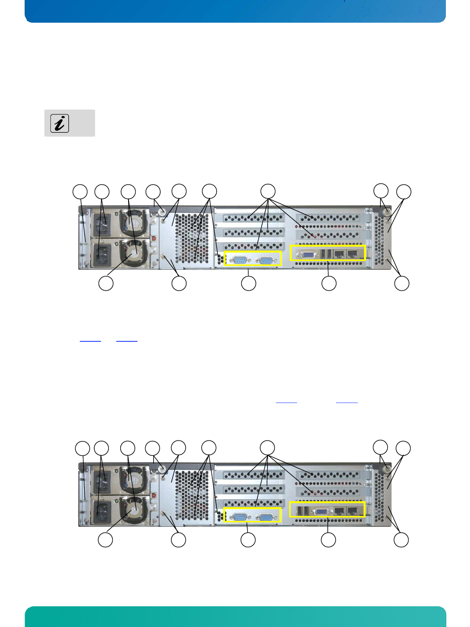
7.2.1. System Configurations with SBC Cards
Fig. 13: Rear side of the KISS 2U V2 with an SBC card (shown with aPCI-760 and a redundant PSU)
Legend for Fig. 13 and Fig. 14:
1 AC inlet connector
2 Fans of the redundant PSU
3 Rear side of the cover with captive knurled
screws
4 Card cage (for SBC and expansion cards) with
fixing screws
5 Air exhaust openings
6 Free slots for expansion cards
7 Onboard interfaces routed to the rear side
8 Interfaces of the SBC card
[PCI-760 (Fig. 13) / PCI-761 (Fig. 14)]
9 Ground stud
Fig. 14: Rear side of the KISS 2U V2 with an SBC card (shown with a PCI-761 and a redundant PSU)
2
3
5
6
3
1
4
9
4
2
8
7
4
4
2
3
5
6
3
1
4
4
9
2
8
7
4
4
18
www.kontron.com