System configuration with motherboard – Kontron KISS 2U X9SCM Low profile User Manual
Page 22
7. Product Description
KISS 2U V2 – User's Guide (Version 1.00)
7.2.2. System Configuration with Motherboard
10
1
2
3
6
6
11
7
4
4
8
9
5
4
12
10
4
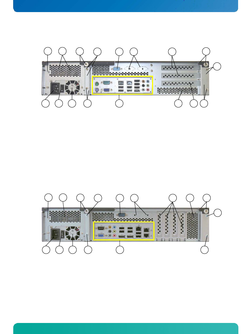
Fig. 17: Rear side of the KISS 2U V2 with a KTQ45/Flex (here with a wide range power supply)
1 AC inlet connector
2 On/Off power switch of the PSU
3 Fan of the Power Supply Unit (PSU)
4 Card cage (for motherboard and expansion cards)
with fixing screws
5 External interfaces of the KTQ45/Flex
motherboard
6 Rear side of the cover with captive knurled screws
7 Slot brackets for expansion cards
8 Cut-outs for optional (customer-specific)
interfaces routed to the rear (9-pin D-SUB
type)
9 Additional serial port (RS232)
10 Air exhaust openings
11 Ground stud
12 Mechanical slot
7.2.3. System Configuration with Motherboard and Low Profile Cards
10
1
2
3
6
6
11
10
7
4
4
4
8
9
5
4
Fig. 18: Rear side of the KISS 2U V2 with a KTQ67/Flex (shown as a configuration for low profile expansion cards)
1 AC inlet connector
2 On/Off power switch of the PSU
(only for wide rage PSU)
3 Fan of the Power Supply Unit (PSU)
4 Card cage (for motherboard and
expansion cards) with fixing screws
5 External interfaces of the
KTQ67/Flex motherboard
6 Rear side of the cover with captive knurled screws
7 Slot brackets for expansion cards
8 Cut-outs for optional (customer-specific) interfaces
routed to the rear (9-pin D-SUB type)
9 Additional serial ports (RS232)
10 Air exhaust openings
11 Ground stud
20
www.kontron.com