Grounding stud, Fan slide-in module and temperature sensor, Side view – Kontron KISS 2U X9SCM Low profile User Manual
Page 25: Fig. 25: grounding stud marked with pe symbol, Fig. 26: unmarked grounding stud, Fig. 27: kiss 2u v2 - side view, Fig. 27, N slide-in module (hot-swap) (see subsection 7.2.6
7. Product Description
KISS 2U V2 – User's Guide (Version 1.00)
7.2.5. Grounding Stud
The grounding stud is located on the rear side of the KISS 2U V2 platform (see Fig. 13, pos. 9 and Fig. 14, pos. 11).
The KISS 2U V2 systems with grounding studs marked with a PE symbol (
by establishing a large-area contact between the grounding stud and an appropriate grounding
connection point.
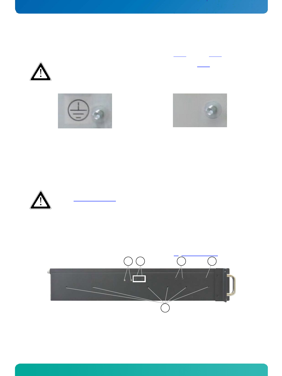
Fig. 25: Grounding stud marked with PE symbol
Fig. 26: Unmarked grounding stud
7.2.6. Fan Slide-In Module and Temperature Sensor
The three system fans are securely installed in a user-friendly, interchangeable fan-slide-in module (Hot-Swap). The fan
slide-in module is mounted in the fan compartment on the front of the device.
The systems fans are temperature-controlled via the temperature sensors which are built in the system. Thus sufficient
airflow is ensured for an optimal, active cooling of the system.
The operation of the KISS 2U V2 platform is permitted only with a functional fan slide-in module (refer
to the “Replacing System Fans” section).
Defective components may be replaced only by Kontron original spare parts.
part number of the fan slide-in module: 1050-8442
7.3. Side View
On the left and right sides of the device, there are six M4 threaded screw holes, for installing the KISS 2U V2 platform in a
19" industrial cabinet using slide rails [not included; refer also to the chapter 11 “Slide Rails (Option)”.]
2
1
2
3
4
Fig. 27: KISS 2U V2 - side view
1 Side view of the KISS 2U V2 platform
3 Fastening screws for the card holder (the
position can be different ; see pos. 2)
2 3x two M3 threaded screw holes used for
mounting of card holder
4 4x M4 threaded screw holes (on both sides)
www.kontron.com
23