4 onboard connectors and headers, 5 board hot swap and installation, Table 3-2 onboard connectors and headers – Kontron AT8242 User Manual
Page 38
22
www.kontron.com
3.4
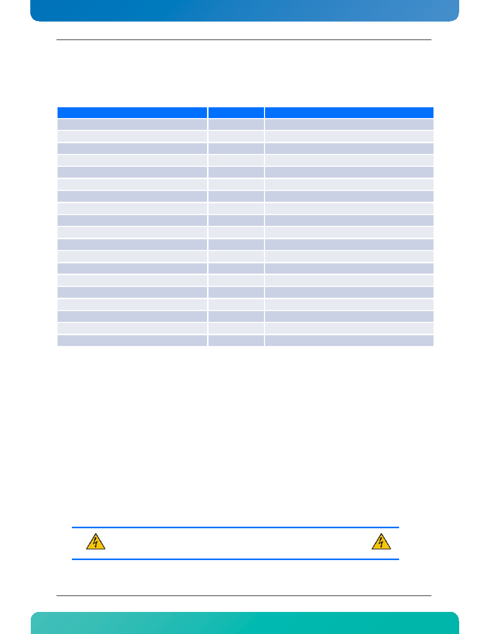
Onboard Connectors and Headers
Table 3-2:Onboard Connectors and Headers
3.5
Board Hot Swap and Installation
Because of the high-density pinout of the hard-metric connector, some precautions must be taken when
connecting or disconnecting a board to/from a backplane:
1 Rail guides must be installed on the enclosure to slide the board to the backplane.
2 Do not force the board if there is mechanical resistance while inserting the board.
3 Screw the front plate to the enclosure to firmly attach the board to its enclosure.
4 Use ejector handles to disconnect and extract the board from its enclosure.
Description
Connector
Comments
Memory Socket NPU0 Channel 1
J1
DDR3 UDIMM Memory Socket
Memory Socket NPU0 Channel 3
J2
DDR3 UDIMM Memory Socket
Memory Socket NPU0 Channel 2
J3
DDR3 UDIMM Memory Socket
Memory Socket NPU0 Channel 0
J4
DDR3 UDIMM Memory Socket
Memory Socket NPU1 Channel 1
J5
DDR3 UDIMM Memory Socket
Memory Socket NPU1 Channel 3
J6
DDR3 UDIMM Memory Socket
Memory Socket NPU1 Channel 2
J7
DDR3 UDIMM Memory Socket
Memory Socket NPU1 Channel 0
J8
DDR3 UDIMM Memory Socket
Debug Connector
J9
eUSB Flash Connector NPU0
J10
eUSB Flash Connector NPU1
J11
Management/Console Port
J13
UC Memory connector
J15
DDR3 SO-UDIMM Memory Socket
RTM Connectors
J31 & J32
Base & Fabric Interface Connector
J20 & J23
Power Connector
P10
Reset Switch
SW1
User Switch
SW2
Handle Switch
SW3
WARNING
Always use a grounding wrist strap before installing or removing the board from a
chassis.