6 external power supply for digital outputs, 7 cable interfacing, Debouncing periods - 4 – Kontron CP383 User Manual
Page 74: System considerations cp383
System Considerations
CP383
Page 6 - 4
© 2004 Kontron Modular Computers GmbH
ID 27784, Rev. 01
27784
.01.VC.040308/162549
P R E L I M I N A R Y
6.5
Process-Side Signal Conditioning for Digital Inputs
Considerations:
1. Input signals presented to the CP383 must be within the ranges specified for signals in
table 1-4 or erroneous results will occur as well as possible damage to the CP383.
6.6
External Power Supply for Digital Outputs
Considerations:
1. Voltage sources presented to the CP383 must be within the ranges specified in table 1-5
or erroneous results will occur as well as possible damage to the CP383.
2. In addition to supplying the current for the logic parts of the power switches which are
linked to the digital outputs, the external voltage supplies also have to supply the current
for the 8 digital output loads per cluster.
6.7
Cable Interfacing
Considerations:
1. No modification to the CP383 itself is permitted.
2. If necessary, cabling to the CP383 CON2 connector should be physically fixed to prevent
strain on the CON2 connector.
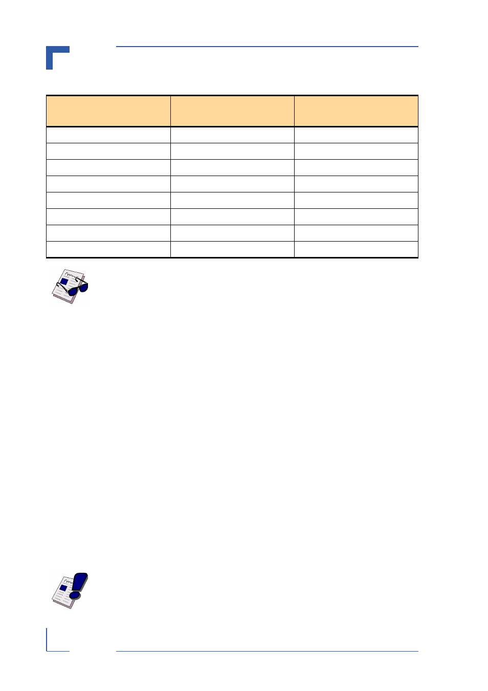
Table 5-1: Debouncing Periods
CLOCK DIVIDER
INPUT SAMPLE CLOCK
@ 33 MHz PCI CLK
INPUT SAMPLE PERIOD
@ 33 MHz PCI CLK
1 (default value - see note below)
33 MHz
30 ns
2^8
128 kHz
8 µs
2^10
32 kHz
32 µs
2^12
8 kHz
128 µs
2^14
2 kHz
0.5 ms
2^16
0.5 kHz
2 ms
2^18
125 Hz
8 ms
2^20
31 Hz
32 ms
Note ...
The clock divider default value is 1. In addition to the choice of debouncing fil-
ters, there is an analog filter implemented on board with an edge frequency at
10 kHz.
Warning!
Each channel has a maximum current of 0.5 A. In situations where many chan-
nels are carrying a high current, separate, larger gauge cables for the external
power supply should be used.