8 hardware debug/test registers, 9 generating interrupts, Hardware debug/test registers - 14 – Kontron CP383 User Manual
Page 60: Generating interrupts - 14, Configuration cp383
Configuration
CP383
Page 4 - 14
© 2004 Kontron Modular Computers GmbH
ID 27784, Rev. 01
27784
.01.VC.040308/162544
P R E L I M I N A R Y
4.4.8
Hardware Debug/Test Registers
These registers are for internal test and debug only. The Common Status Register contains
logic version and PCB version. The Common Debug Register is a read/write register without
any further functionality besides the front panel monitor and control LEDs.
4.4.9
Generating Interrupts
For digital outputs, a detected fail flag set in the register can trigger an interrupt. For digital
inputs, a detected event or in other words any event flag set in the Input Status Register can
trigger an interrupt. Thus, any input can be enabled individually for interrupt generation.
Independent of the interrupt cause, a board interrupt is handled on the hardware level always
in the same way.
After having set the input control registers where compare data and events are defined, inter-
rupts can be enabled individually within the Input IRQ Enable Register. Within the interrupt ser-
vice routine, interrupts should be handled as follows.
1. Check if the board is the cause of the interrupt (General Interrupt Pending is set).
2. If yes, check the reason for the interrupt by reading the fail flag in the output status reg-
ister and by reading the digital input status register.
3. Reset the corresponding Flag by writing a "1" to a set status bit (fail) or to the Input Event
Flag.
4. Reset the board’s IRQ by resetting the General Interrupt Pending Bit by writing a "1" to
that status bit.
5. Return from Interrupt.
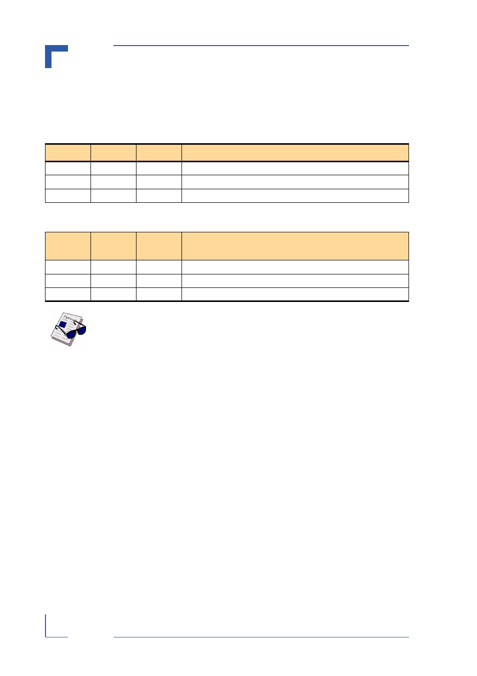
Table 4-15: Hardware Debug Register
BITS
TYPE
DEFAULT
FUNCTION
31-2
r/w
0
Reserved
1
r/w
0
FAIL
0
r/w
0
RUN
Table 4-16: Hardware Status Register
BITS
TYPE
DEFAULT
*
FUNCTION
31-16
r
0
Reserved
15-8
r
00
HW Version (PCB Index)
7-0
r
01
Logic Version
Note ...
The HW version starts with 0, the Logic version starts with 1. At each further
release it will be incremented by 1.