4 detecting input events, Detecting input events - 11, Configuration cp383 – Kontron CP383 User Manual
Page 56
Configuration
CP383
Page 4 - 10
© 2004 Kontron Modular Computers GmbH
ID 27784, Rev. 01
27784
.01.VC.040308/162544
P R E L I M I N A R Y
4.4.4
Detecting Input Events
Detecting events on input means that the CP383 hardware can supervise the input ports upon
their changing state and without being continuously polled. This mode is controlled by three
control registers. In the Input Event Mask Register, individual input events can be enabled
which should be monitored. In the Input Polarity Register the direction of the change-of-state
is set. Detected events are reported in the corresponding Input Event Status Register.
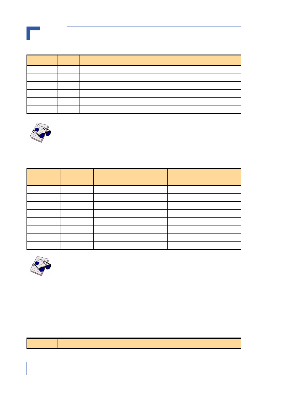
Table 4-4: Input Control Register
BITS
TYPE
DEFAULT
FUNCTION
31-8
R/W
0
RESERVED
7
r/w
0
Input enable
6
r/w
0
Event detect enable
5
r/w
0
Latch mode enable
4
r/w
0
Pattern detect enable
2-0
r/w
000
Debounce control deb [2 ... 0]
Note ...
The inputs are sampled through the debouncer after the Input Enable bit is set.
Additional features such as event and pattern detection and latch mode are also
enabled in the input control register, after being configured within the corre-
sponding mode registers.
Table 4-5: Programmable Input Sample Rates
deb [2 ... 0]
CLOCK
DIVIDER
INPUT SAMPLE CLOCK
@ 33MHz PCI
INPUT SAMPLE PERIOD
@ 33MHz PCI
000
1
33 MHz
30 ns
001
2^8
128 KHz
8 µs
010
2^10
32 KHz
32 µs
011
2^12
8 KHz
128 µs
100
2^14
2 KHz
0.5 ms
101
2^16
0.5 KHz
2 ms
110
2^18
125 Hz
8 ms
111
2^20
31 Hz
32 ms
Note ...
The clock divider default value is 1. In addition to the choice of debouncing fil-
ters, there is an analog filter implemented on the board with an edge frequency
at 10 kHz.
Table 4-6: Input Event Mask Register
BITS
TYPE
DEFAULT
FUNCTION