3 digital output signal properties, 1 channels, 2 connection of external supply – Kontron CP383 User Manual
Page 51: 3 digital output signal properties - 5, Channels - 5, Connection of external supply - 5, Cp383, Cp383 configuration, Con2
CP383
Configuration
ID 27784, Rev. 01
© 2004 Kontron Modular Computers GmbH
Page 4 - 5
27784
.01.VC.040308/162543
P R E L I M I N A R Y
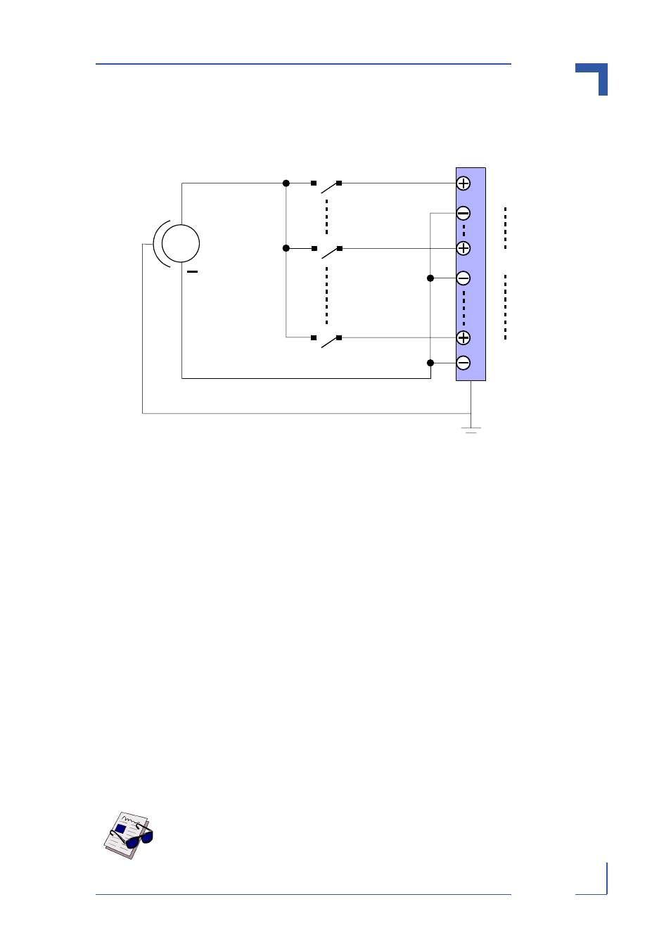
Figure 4-4: Configuration Diagram for All Input Channels
4.3
Digital Output Signal Properties
In addition to the output signal type and its range, which have been specified in table 1-5, sys-
tem integrators must be aware of certain output configuration requirements for the CP383. The
following paragraphs provide some information regarding individual connection configuration
requirements.
4.3.1
Channels
The CON2 connector of the CP383 provides only one output pin per channel. This is illustrated
in figure 2-2, which shows the front panel connector pinout with the 16 output channels shown
starting at the middle of the connector with channel 0 (DIGOUT A cluster).
The following sections address the basic requirements.
4.3.2
Connection of External Supply
The CP383 requires an external voltage for operation.
The input connection for this voltage is realized via the 62-pin front panel connector CON2. The
pinout of this connector is provided in table 2-1.
The two clusters have split supply planes, so that it is possible to provide each cluster (DIGOUT
A and DIGOUT B clusters) with a separate voltage, with different voltage values within the de-
fined range (see also table 1-1)..
Note ...
Each channel has a maximum current of 0.5 A. In situations where many chan-
nels are carrying a high current, separate, larger gauge cables for the external
power supply should be used.
Ch 0
Ch n
Ch 15
+
V
Digital Sensors
CP383
CON2