Configuration, 1 jumper settings, 2 digital input signal requirements – Kontron CP383 User Manual
Page 49: 1 channels, 2 signal characteristics, Configuration - 3, Channels - 3, Signal characteristics - 3, High low, Cp383 configuration
CP383
Configuration
ID 27784, Rev. 01
© 2004 Kontron Modular Computers GmbH
Page 4 - 3
27784
.01.VC.040308/162543
P R E L I M I N A R Y
4.
Configuration
This chapter provides information for configuring the CP383 board for operation.
4.1
Jumper Settings
The CP383 does not have any jumpers which require configuring.
4.2
Digital Input Signal Requirements
In addition to the input signal type and its range, which have been specified in table 1-4, system
integrators must be aware of certain input configuration requirements for the CP383. The fol-
lowing paragraphs provide information regarding individual connection configuration require-
ments.
4.2.1
Channels
The CON2 connector of the CP383 provides two input pins per channel. This allows each chan-
nel to be configured separately as required. This is illustrated in figure 2-2, which shows the
front panel connector pinout, with the 16 input channels shown starting at the top of the con-
nector with channel 0 (DIGIN cluster).
The following sections address the basic requirements.
4.2.2
Signal Characteristics
The signals are differential and the specified voltage ranges illustrated in the following figure
should be observed.
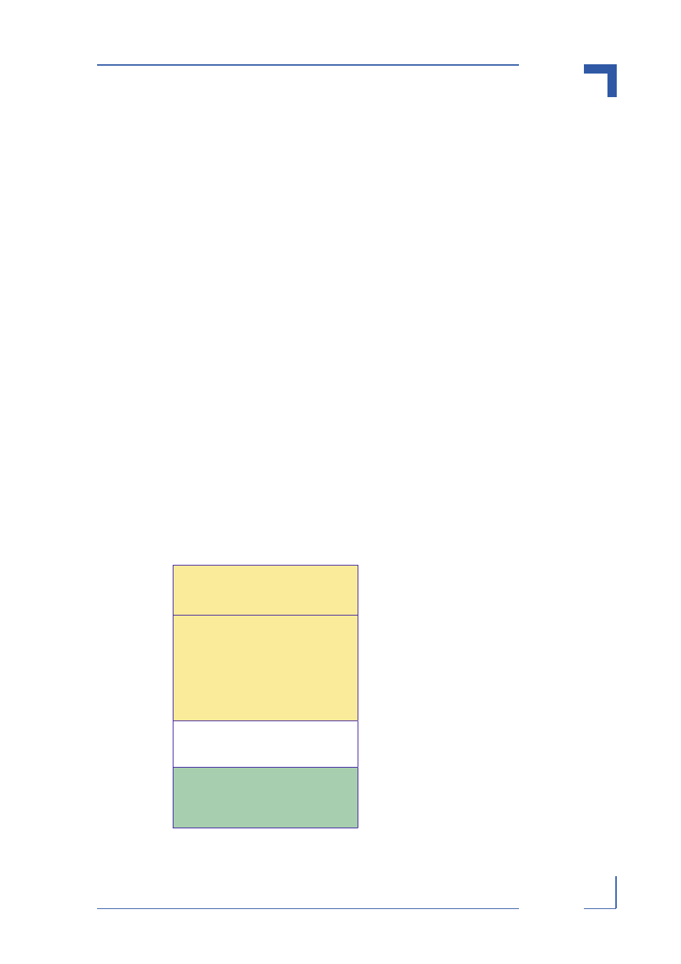
Figure 4-1: Voltage Ranges
HIGH
LOW
+30V Maximum
+24V
standard
+11V
+5V
-3V
LOW is < +5V
HIGH is > +11V
INDETERMINATE ZONE