Cp383 introduction – Kontron CP383 User Manual
Page 27
CP383
Introduction
ID 27784, Rev. 01
© 2004 Kontron Modular Computers GmbH
Page 1 - 11
27784
.01.VC.040308/162542
P R E L I M I N A R Y
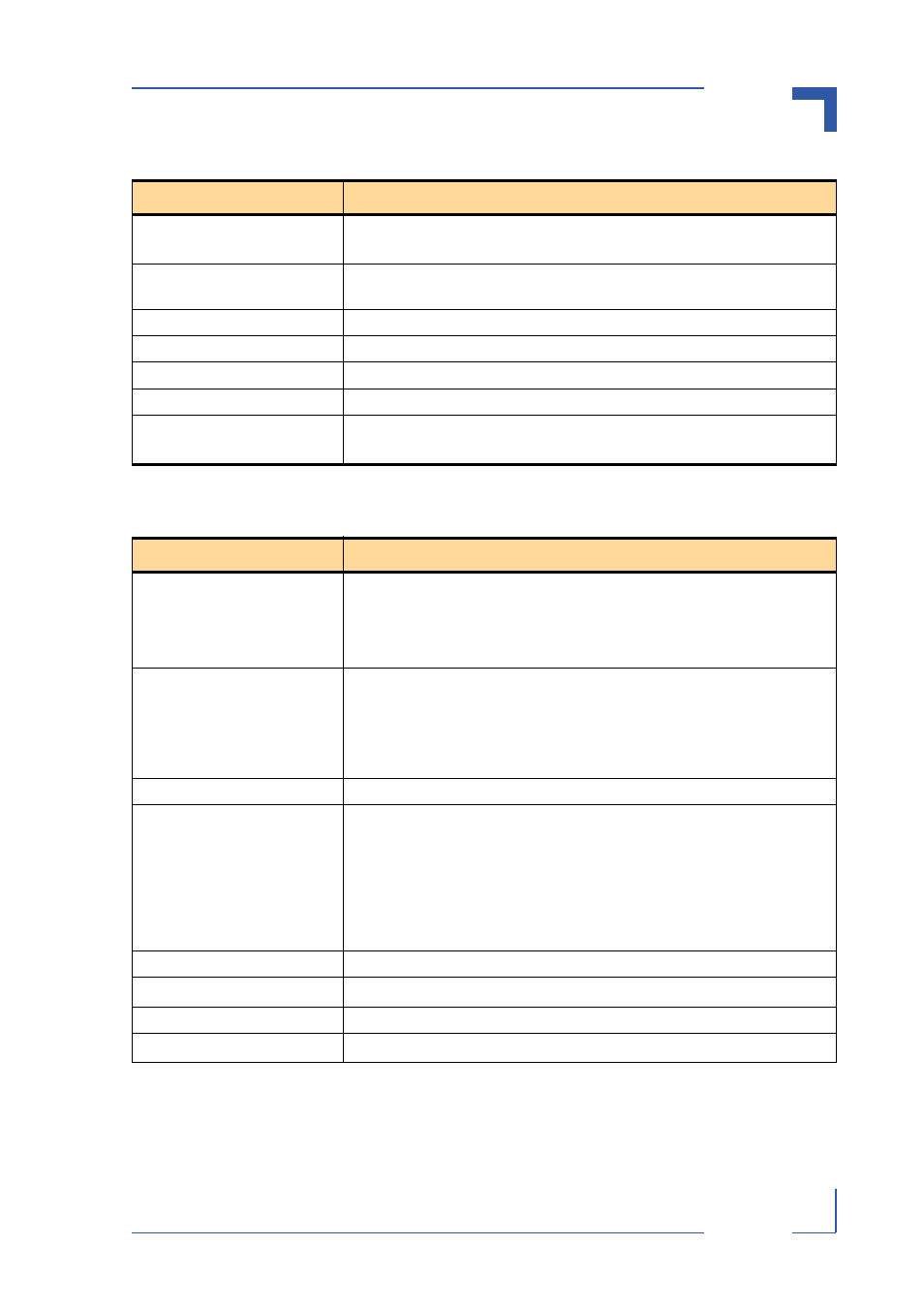
Table 1-4: CP383 Digital Input Specifications
TYPE
DESCRIPTION
Input Voltage Range
Low:
-3V to +5V
High: +11V to +30V
Channels
16 channels isolated from the system side. They do not share common GND
or VCC.
Channel Connections
2 pins per channel; differential input
Input Filter (edge frequency)
10 kHz
Input Protection
8 kV ESD
Isolation
2 kV process to system
Input Impedance
Minimum:
1.5 k ohm
Maximum: 6 k ohm at 30V
Table 1-5: CP383 Digital Output Specifications
TYPE
DESCRIPTION
Output Voltage Range
Low state: =< +1.5 V
High state: > +8.0 V and < +35 V
Current per channel: max. 0.5 A
Leakage current: 20 µA
Channels
16 channels grouped into two clusters of eight channels each
Common GND and VCC for each output cluster
The output channels are isolated from the system side and share common
GND and VCC within the clusters. The two output clusters are galvanically iso-
lated from each other.
Channel Connections
1 pin per channel, single-ended
External Reset
All digital output channels of a cluster can be collectively switched low by
using one of the following methods:
•
externally via the EXTRESET signal
•
internally on request from the application via the DIO ProComm
Controller
This results in all outputs being kept switched low irrespective of the input
data for these channels.
External Voltage (VCC)
+9.5 V to +35 V
Switch “On” Resistance
R
ds,on
= 1.8 ohm
Max. Output Frequency
2.5 kHz
System Switching Delay Time
T
d,on
= 4 µs, T
d,off
= 90 µs