Elecraft KPA3 Power Connector Replacement Manual User Manual
Page 9
KPA3 Connector Replacement
Page 9 of 16
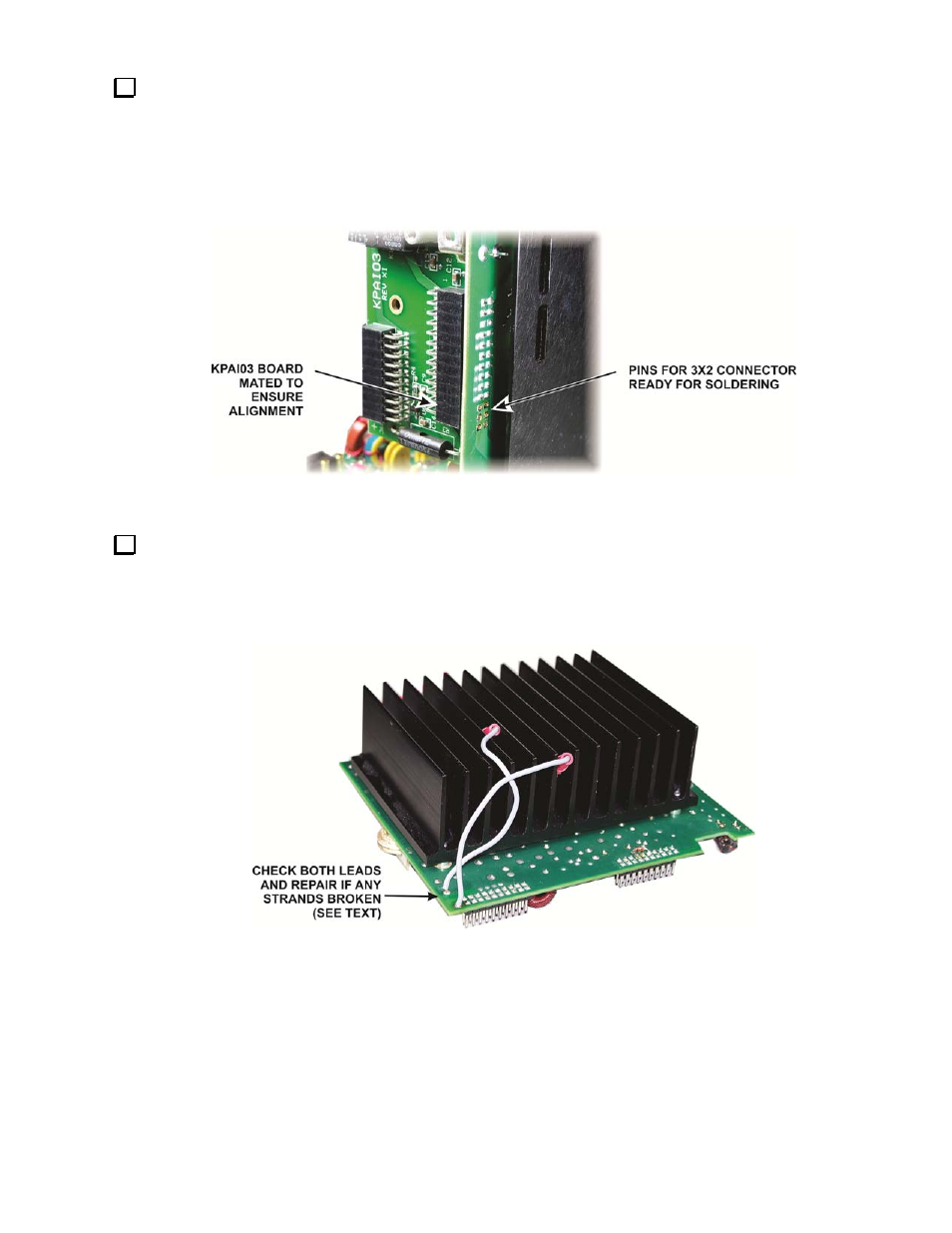
Use your de-soldering tool to clean the solder out of the pads and then insert the replacement 3X2 connector
in the holes. Be sure the pad holes are clear so the pins fit without excess pressure. If you push too hard on the
plastic base, the pins in the new connector will be pushed up out of line. Once the connector is in place and firmly
against the circuit board, plug the KIO3 interface board into the connectors to ensure they are properly aligned.
(You can stand the K3 on its side feet to gain easy access to both sides of the pc board.) Solder all six pins. Use a
hot enough iron to flow solder within a few seconds to avoid softening the plastic holder. When finished, remove
the KPAIO3 board.
Figure 15. 3X2 Connector Ready for Soldering.
On the KPA3 module, inspect where the two leads to the circuit breaker connect to the board for any signs of
discoloration from heat or broken wires (see Figure 16). If broken or loose strands are found, remove and re-
solder the lead to the board pads. You will need to clean out the pad holes completely. The wires are a tight fit,
making it easy for loose strands to be left out. Make sure all the strands are soldered in place. The wires are long
enough to cut and re-strip sufficient length to pass through the solder pad.
Figure 16. KPA3 Circuit Breaker Leads.