Elecraft KPA3 Power Connector Replacement Manual User Manual
Page 11
KPA3 Connector Replacement
Page 11 of 16
If you removed the KXV3 board earlier, replace it now. Be sure all the pins engage the J66 on the K3 RF
board. They do not fully mate. You can adjust the position after the rear panel is installed. Also you may notice
that one pin is missing. That is normal. The opposing socket is plugged to help you avoid mis-alignment.
Replace the rear panel on the K3 (see Figure 12 on pg 7) using the hardware you removed earlier:
Two 4-40, 3/16” (4.8mm) black pan head screws on the bottom lip.
One 4-40, 3/16” (4.8mm) black flat head screw on the top lip.
Ground thumb screw with two #6 flat washers.
One 4-40, 3/8” (9.5mm) black flat head screw with #4 lock washer and 4-40 nut connecting the rear panel
to the KPA3 shield.
Reconnect the ANT connector(s) to the KAT3 or KANT3 (Figure 11, pg 7). If you have the KAT3 ATU, be
sure you connect ANT1 to the connector closest to the rear panel. Use a DMM if needed to confirm you have the
connectors in the correct locations.
If present, replace the KXV3 rear panel and secure the assembly using the two 4-40, 1/2" (13mm) screws, #4
lock washers and 4-40 nuts that you removed earlier (Figure 9, pg 6).
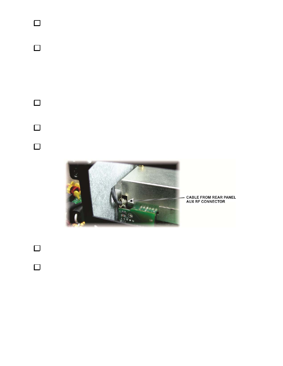
If the sub-receiver is installed and you disconnected the cable to the rear-panel AUX RF connector, replace it
(Figure 19). If this cable ran to the KAT3 module instead, be sure it is still plugged in at both ends.
Figure 19. Replacing AUX RF Cable in Sub Receiver.
Plug the KIO3 board into J16 on the K3 RF board (Figure 8, pg 5) and, if you removed it, the top standoff
using a 1/4” (6.4mm) zinc pan head screw and lock washer.
Replace the Remote I/O board, plugging it into the KIO3 board (Figure 7, pg 5). Adjust the position of the
audio connectors so they fit through the holes in panel. Secure the panel with two 1/4" (6.4mm) black pan head
screws.