Elecraft KPA3 Power Connector Replacement Manual User Manual
Page 15
KPA3 Connector Replacement
Page 15 of 16
Replace the fan panel using the 4-40, 3/16” (4.8mm) black pan head screws you removed earlier (see Figure
2, pg 2).
If the K3 is equipped with the K144XV option, before attaching the fan panel to the K3 rear panel,
first route the coax TMP cable from the ANT3 connector across the top of the KPA3 module board
and through the opening in the shield behind theKIO3 board and reconnect it to the 2M ANT
connector on the K144XV module.
Be sure the connectors on the circuit breaker fit snugly. If they are loose, squeeze them gently with
your needle nose pliers to tighten the fit. It does not matter which wire goes to each terminal on the
circuit breaker.
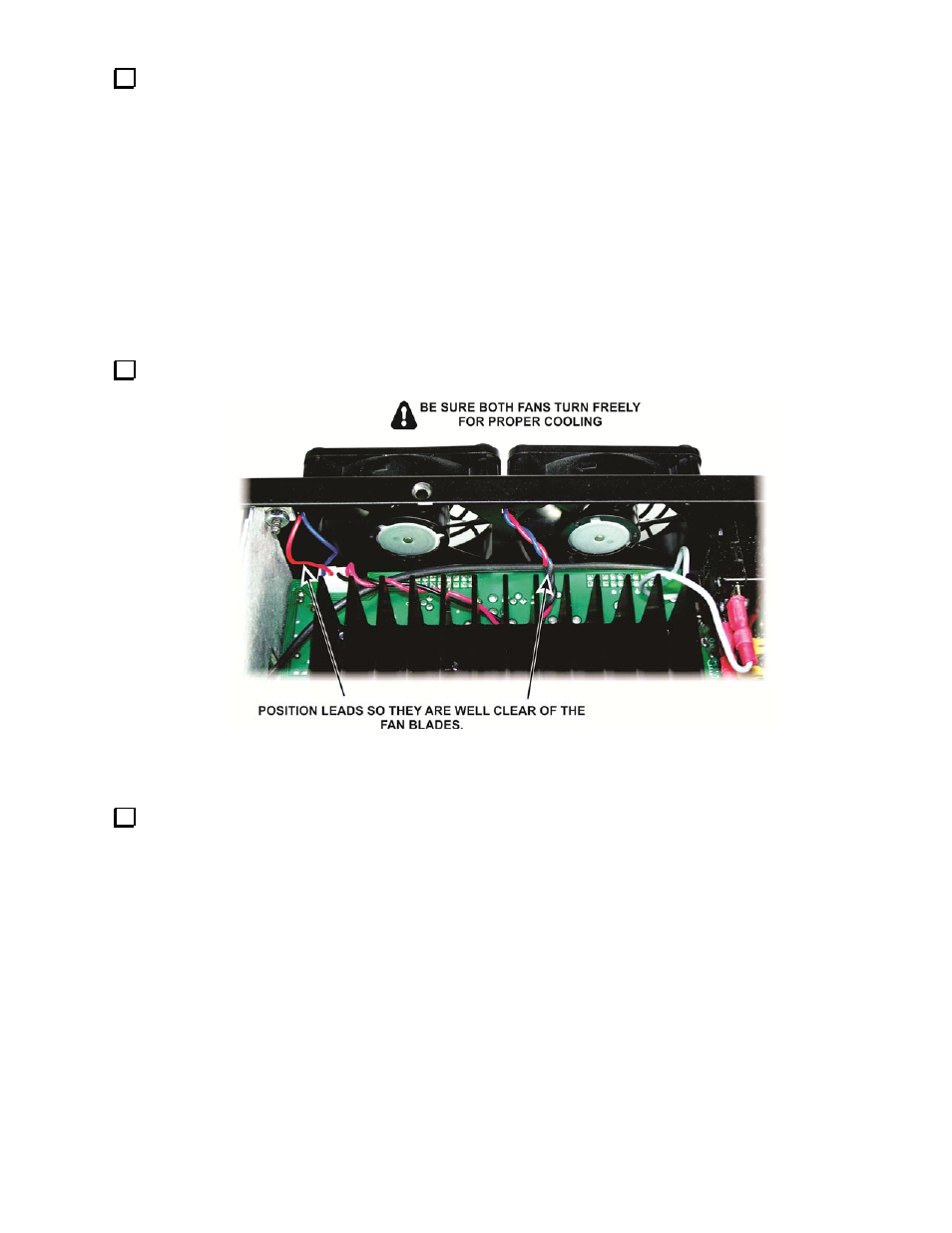
Orient the fan connectors so the red wires are to the left, looking at the assembly from the rear. The
colors are marked on the circuit board as well. Installing them backward will cause the fans to run in
reverse, severely limiting the PA cooling.
Dress the fan leads so they are well clear of the blades (see 15). Ensure both fans turn freely.
Figure 25. Positioning the Fan Leads.
Use your DMM to measure the resistance across the red and black terminals of the 12VDC IN connector on
the K3 rear panel. It should be greater than 2,000 ohms. What you are checking for is to ensure there isn’t a dead
short across the 12V input created by a solder bridge or other problem resulting from the connector replacement.