Elecraft KPA3 Power Connector Replacement Manual User Manual
Page 10
KPA3 Connector Replacement
Page 10 of 16
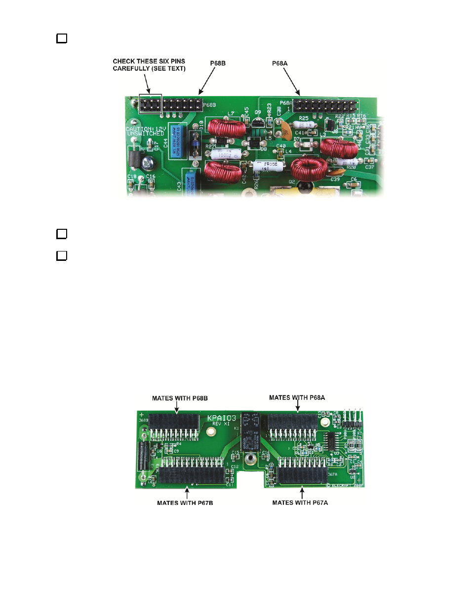
On the KPA3 module, inspect the six pins of P68B (see Figure 17) for corrosion or discoloration from heat
just as you did on P67B earlier.
Figure 17. KPA3 Connectors.
Replace the pins with the 3X2 replacement connector just as you did on the K3 main RF board earlier.
If any of the pins you removed showed corrosion or discoloration, the female connectors in the KPAIO3
board are damaged as well. The female connectors are already gold plated, and do not need to be replaced unless
heat or corrosion is evident on the corresponding male connectors (see Figure 18). If needed, replace the
connectors one at a time as follows:
Cut the exposed leads to free the main body.
Remove each lead and clear the hole in the board of all solder.
Carefully position the replacement connector so it is flat against the KPAIO3 board and is aligned with
the silk-screened outline on the board, and then solder one lead at each end of the connector.
Check the position of the connector and adjust it as needed by heating the soldered leads.
Gently place it against the mating connectors on the K3 or KPA3 boards to confirm the alignment.
Solder all the remaining leads.
Figure 18. KPAIO3 Connectors.