Elecraft KPA3 Power Connector Replacement Manual User Manual
Page 8
KPA3 Connector Replacement
Page 8 of 16
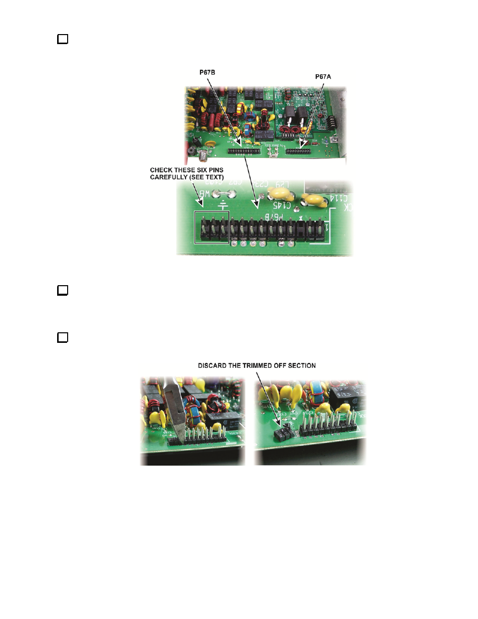
Locate male multi-pin connectors P67A and P67B near the back edge of the K3 main (RF) circuit board (see
Figure 13). Inspect the six pins on P67B at the end of the connector for signs of corrosion or discoloration
indicating that it has overheated.
Figure 13. Connector Locations on K3 RF Board.
One of the gold plated 3X2 male connectors will replace these six pins. Begin by removing the individual
pins. Grip each pin near the tip. Use cutters instead of pliers to minimize the heat transfer to the tool. Pull on the
pin while heating the corresponding solder pad on the bottom of the connector. As the plastic softens, the pin will
pull out.
Cut away the plastic housing for the six pins with your flush cutters (Figure 14). A sharp knife or razor blade
can be used as well if you take care not to damage the pc board.
Figure 14. Cutting the Connector Housing.
- KX3 Owner's Manual (58 pages)
- KX3 Assembly Manual (47 pages)
- KX3 Assembly Manual Errata (5 pages)
- KX3-2M (30 pages)
- KX3-PCKT (2 pages)
- KX3 Mobile Installation And Operation Guide (17 pages)
- KX3 Guide for Blind Operators (7 pages)
- KX3 Quick Reference (2 pages)
- K3 Programmers Reference (26 pages)
- KX3 Speaker Grille Instructions (9 pages)
- KXFL3 Filter Option (12 pages)
- KXFL3 Filter Option Errata (2 pages)
- KXAT3 (5 pages)
- KXBC3 (13 pages)
- KXPD3 (4 pages)
- Proset Boom Headset (1 page)
- PX3 Owner's Manual (53 pages)
- PX3 Owners Manual Errata (2 pages)
- KXPA100 Manual (55 pages)
- KXPA100 Assembly Manual (27 pages)
- KXPA100 Assembly Errata (1 page)
- KXPA100 Programmers Reference (24 pages)
- KXAT100 Installation Manual (17 pages)
- KX1 Manual (96 pages)
- KXAT1 (12 pages)
- KXPD1 (7 pages)
- KXB30 (8 pages)
- KXB3080 (20 pages)
- K1 (91 pages)
- K1 1.09 F/W (1 page)
- KNB1 Manual (8 pages)
- KAT1 Manual (15 pages)
- KFL1-2 (2 pages)
- KTS1 (1 page)
- KBT1 Manual (8 pages)
- KBT1 Manual Errata (2 pages)
- K1BKLTKT LCD Mod Kit (6 pages)
- K2 Owner's Manual (171 pages)
- K2 Owner's Manual Errata (1 page)
- K2 PLL (4 pages)
- K2ATOBKIT (15 pages)
- K2ATOBKT (2 pages)
- K2 Keying Modification Instructions (4 pages)
- KPA100 Manual (74 pages)
- KPA100 Shield Upgrade (3 pages)