K3 kit builders, Replacing the knb3 module, Replacing the krx3 module – Elecraft KPA3 Manual User Manual
Page 18
18
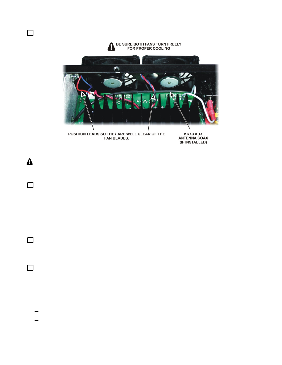
Dress the fan leads so they are well clear of the fan blades. Check to ensure both fans turn freely.
Figure 18. Positioning the Fan Leads.
K3 KIT BUILDERS:
Skip the following steps. Resume with Replacing the Covers on page 19
Replacing the KNB3 Module
Replace the standoff and the KNB3 module you removed earlier (see Figure 5). When mounting the
standoff on the RF board, be sure to place one lock washer under the screw head on the bottom of the board, and
two lock washers between the standoff and the top of the board. A fourth lock washer goes under the screw
holding the KNB3 module itself.
Replacing the KRX3 Module
If your K3 is not equipped with the KRX3 Subreceiver, go directly to Replacing the Covers below to continue.
If your KRX3 installation uses the Auxiliary Antenna input to the KRX3, a coaxial cable will be present
that runs from the KAT3 or from a connector on the rear panel AUX RF connector. Refer to your KRX3
Subreceiver Installation and Operation manual, Auxiliary KRX3 Antenna Input (Optional) section for
instructions on how to route this cable across the KPA3 enclosure to reach the KRX3 module.
Turn to your KRX3 Subreceiver Installation and Operation manual, Installing the KRX3 Subreceiver
Module section to replace the KRX3 module. Be especially careful to do the following as described in that
procedure:
Be sure the cover on battery BT1 on the K3 RF board is in place. The cover is essential to avoid
shorting the battery. The outer rim of the battery is the positive terminal, and may come in contact with
the grounded bottom of the KRX3 enclosure if the cover is not in place.
Be sure all the TMP cables are properly connected or your K3 will not operate properly.
Be sure the TMP cable to J85 on the subreceiver module is routed as shown to prevent signal leakage
between the KRX3 and the K3 main receiver.