Caution – Elecraft KPA3 Manual User Manual
Page 15
15
Install the 20A circuit breaker in the small hole with the pushbutton on the same side as the fans as shown
in Figure 13.
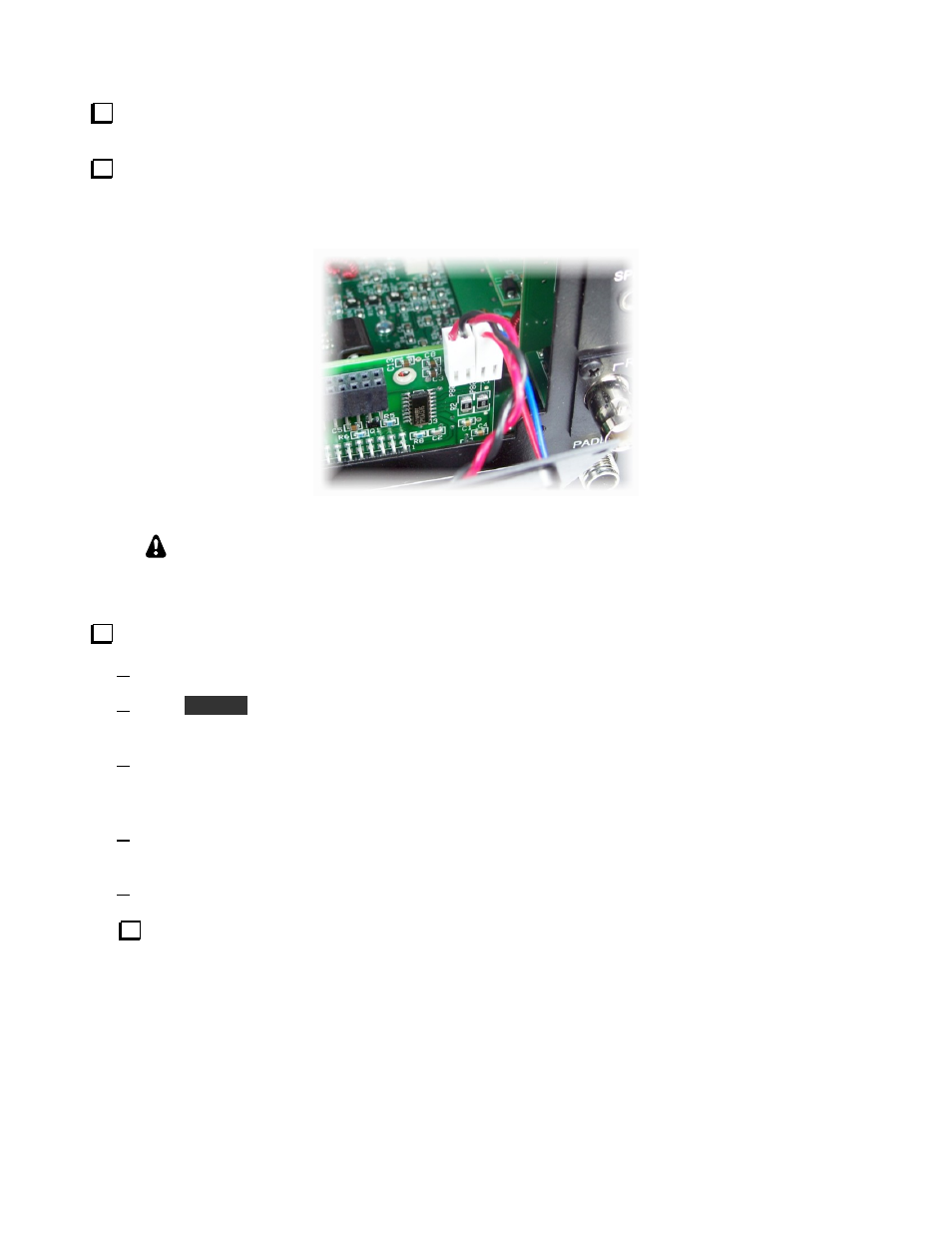
Position the fan panel near the rear opening and plug the fan leads into the connectors in the upper right
corner of the KPAIO3 board as shown in Figure 14. Be sure to orient the connectors so the red lead is to the left
as indicated on the board. If the connectors don’t want to slide onto the pins, check to see if there is any extra
plastic on the side facing the board. If so, trim it smooth with a hobby knife or your diagonal cutters.
Figure 14. Connecting Fans to the KPAIO3 Board.
CAUTION:
If you removed a KRX3 subreceiver module, be sure the loose TMP
cables have been removed or the metal TMP connectors are fully insulated with electrical
tape before proceeding. Otherwise accidental shorts may destroy circuits in your K3.
Connect a power supply to your K3 and test the fans and KPAIO3 interface control as follows:
Press the POWER button to turn the K3 on.
Hold
C O N F I G
to select the Configuration menu, then turn VFO B to KPA3. Normally, the display will
indicate NOT INST (not installed).
Turn the VFO A knob to PAIO ON, then turn it further to PAIO TST. When moving between ON and
TST, you should hear a relay click on the KPAIO3 board. If you don’t, press the K3 POWER button to
switch it off, then on again and retry the test.
Turn the VFO A knob on past TST to FN1, then FN2, FN3 and FN4. The fans should start turning at
FN1 and increase speed as you continue to FN4.
Turn the K3 off and disconnect the power supply.
Unplug the fans and set them aside for now.