Caution, Removing the knb3 module – Elecraft KPA3 Manual User Manual
Page 10
10
Hold the KRX3 module by the two brass knurled nuts on the top, and lift it straight up to gain access to the
small TMP coaxial connectors plugged into the module. There are two along the front. There may be one at the
back as well, depending upon the options installed. As you lift the KRX3 module, it will unplug from two small
interface circuit boards. One is at the front and the other is at the rear. These small boards may come out with
the module or they may remain attached to the K3 main RF board.
Unplug the TMP coaxial cables leading to the KRX3 module, then lift the module free and set it aside.
Locate the two small interface circuit boards that fit between the connectors on the KRX3 module and the
connectors on the K3 RF board. Remove them and put them in a safe place.
Unplug and remove the loose TMP cables that were connected to the KRX3 module. If your K3 is equipped
with a cable connected to a BNC connector at the rear panel AUX RF input, this cable will not unplug. It is
permanently attached to the BNC connector Wrap the metal TMP connector in insulating tape to ensure it
cannot short to any circuits inside the K3.
CAUTION:
You will apply power to make tests before reinstalling the KRX3 module
again. If the loose cables are not removed or insulated to prevent shorts as described in the
previous step, you may destroy circuits in your K3 when you apply power.
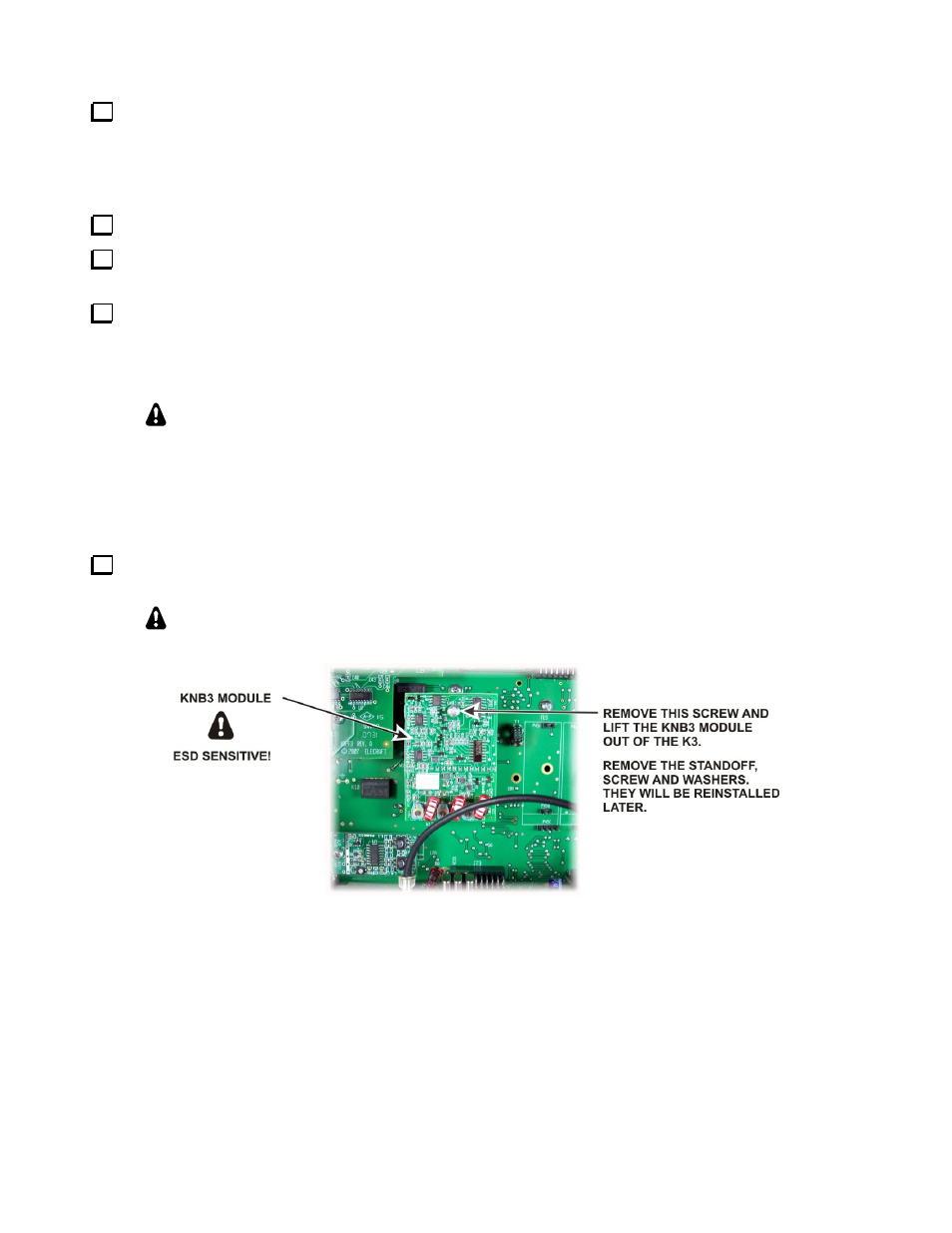
Removing the KNB3 Module
KNB3 module must be removed to provide clearance needed to install the KPA3 shield in the following section.
Remove the KNB3 module, the standoff, screw and washers from the RF board (see Figure 5). They will be
reinstalled later.
CAUTION:
The KNB3 module is ESD sensitive. Put it in a safe place until you
reinstall it.
Figure 5. Removing the KNB3 Module.