Elecraft KPA3 Manual User Manual
Page 13
13
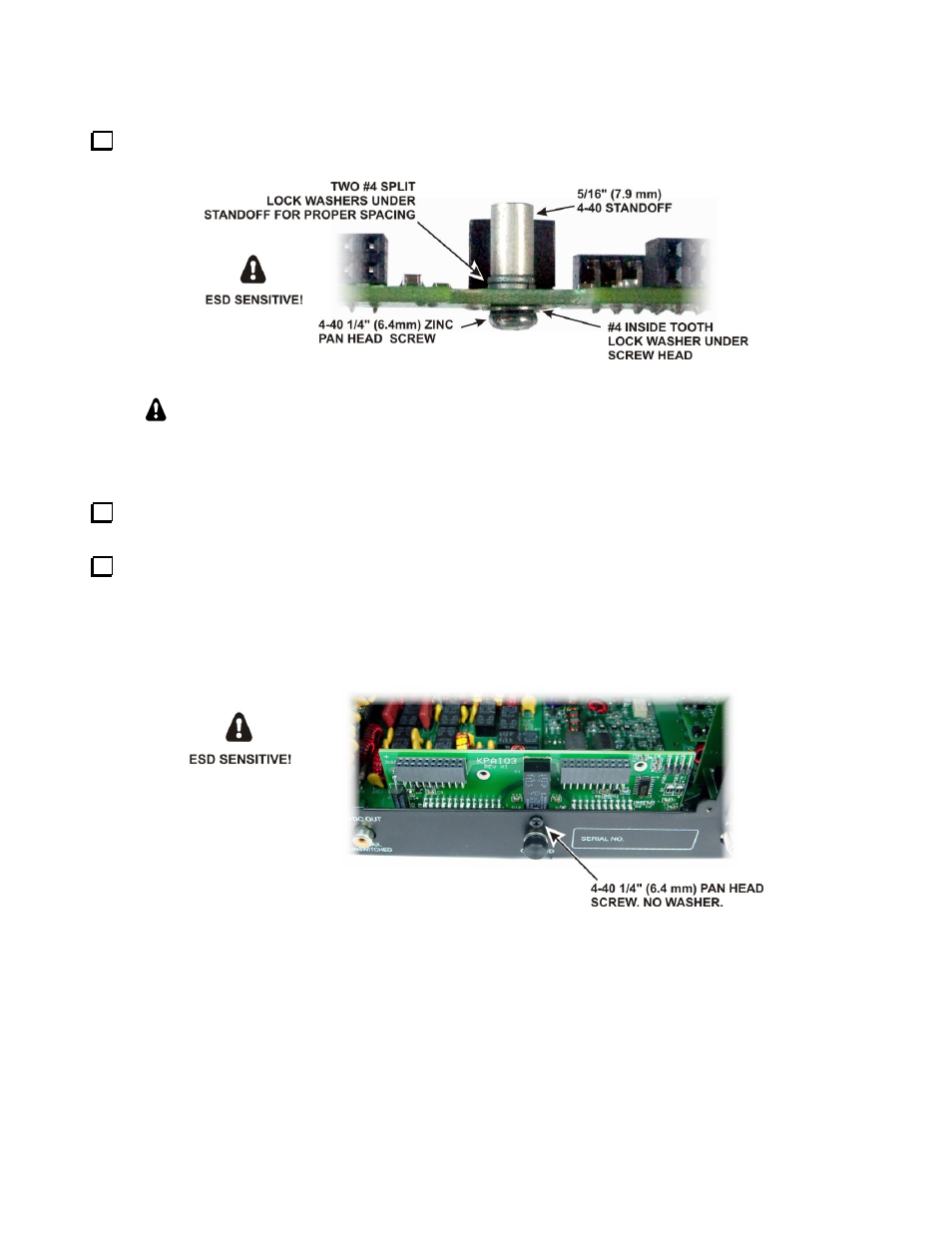
On the KPAI03 board, install a 5/16” (7.9 mm) 4-40 standoff near K1 as shown in Figure 10. Use the exact
hardware shown. This is important so that the height of the standoff is correct when it is mounted in the K3.
Figure 10. Installing Standoff on the KPAIO3 Board.
As you install components and reassemble your K3, be sure all the screws are in place
and secure, but do not over tighten them. Failure to tighten all screws may result in poor
shielding of sensitive components, resulting in possible noise or birdies in the receiver as well
as other difficult-to-trace problems.
If you are adding the KPA3 after assembling your K3 from a kit, remove the rear section of the bottom
cover (see Figure 2 on page 8) in order to properly support the RF board in the following step.
Install the KPAIO3 board just inside the opening in the rear panel as shown in Figure 11. Connector J67A
on the KPAIO3 mates with P67A on the RF board, and J67B on the KPAIO3 mates with P67B on the RF board.
These connectors may fit very tightly. Press one side then the other as needed to fully mate the connectors
while supporting the RF board from below with your fingers. When the connectors are fully mated, the
standoff on the KPAIO3 will line up with the hole in the back panel. Secure the KPAIO3 with a 4-40 1/4” (6.4
mm) black pan head screw. Do not use a washer.
Figure 11. Installing the KPAIO3 Module.